
Isometric projections of figures. Tutorial: Projection drawing, axonometry
Construction of the third view according to two given
When constructing a view on the left, which is a symmetrical figure, the plane of symmetry is taken as the reference for the dimensions of the projected elements of the part, depicting it as an axial line.
The names of the views in the drawings made in the projection relationship are not indicated.
Construction of axonometric projections
For visual images of objects, products and their components unified system design documentation (GOST 2.317-69), it is recommended to use five types of axonometric projections: rectangular - isometric and dimetric projections, oblique - frontal isometric, horizontal isometric and frontal dimetric projections.
By orthogonal projections of any object, you can always build its axonometric image. When axonometric constructions are used geometric properties flat figures, features of the spatial forms of geometric bodies and their location relative to the planes of projections.
General order construction of axonometric projections the following:
1. Select the coordinate axes of the orthogonal projection of the part;
2. Build axonometric projection axes;
3. Build an axonometric image of the main shape of the part;
4. Build an axonometric image of all elements that determine the actual shape of this part;
5. Build a cutout of a part of this part;
6. Put down the dimensions.
Rectangular geometric projection
The position of the axis in a rectangular isometric projection is shown in fig. 17.12. The actual distortion coefficients along the axes are 0.82. In practice, the given coefficients equal to 1 are used. In this case, the images are enlarged by 1.22 times.
Methods for constructing isometric axes
The direction of axonometric axes in isometry can be obtained in several ways (see Fig. 11.13).

The first way is with a 30° square;
The second way is to divide a circle of arbitrary radius into 6 parts with a compass; straight line O1 is the ox axis, straight line O2 is the oy axis.
The third way is to build the ratio of parts 3/5; set aside five parts along the horizontal line (we get point M) and down three parts (we get point K). Connect the resulting point K to the center O. PKOM is 30 °.
Ways to build flat figures in isometry
In order to correctly build an isometric image of spatial figures, it is necessary to be able to build an isometry of flat figures. To build isometric images, follow these steps.
1. Give the appropriate direction to the x and y axes in isometry (30°).
2. Set aside on the x and y axes natural (in isometry) or abbreviated along the axes (in dimetry - along the y axis) the values of the segments (coordinates of the vertices of the points.
Since the construction is carried out according to the given distortion coefficients, the image is obtained with an increase:
for isometry - 1.22 times;
the construction progress is given in Figure 11.14.
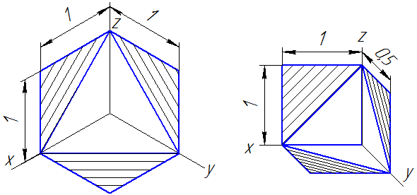
On fig. 11.14a orthogonal projections of three flat figures are given - a hexagon, a triangle, a pentagon. On fig. 11.14b built isometric projections of these figures in different axonometric planes - how, yoz.

Construction of a circle in rectangular isometry
In rectangular isometry, the ellipses depicting a circle of diameter d in the hou, xz, yoz planes are the same (Fig. 11.15). Moreover, the major axis of each ellipse is always perpendicular to the coordinate axis, which is absent in the plane of the depicted circle. Major axis of the ellipse AB = 1.22d, minor axis CD = 0.71d.
When constructing ellipses, the directions of the major and minor axes are drawn through their centers, on which, respectively, segments AB and CD are plotted and straight lines parallel to the axonometric axes, on which segments MN are plotted, equal to the diameter of the depicted circle. The resulting 8 points are connected according to the pattern.

In technical drawing, when constructing axonometric projections of circles, ellipses can be replaced by ovals. On fig. 11.15 shows the construction of an oval without defining the major and minor axes of the ellipse.

The construction of a rectangular isometric projection of a part, given by orthogonal projections, is carried out in the following order.
1. On orthogonal projections, coordinate axes are selected, as shown in fig. 11.17.

2. Build the coordinate axis x, y, z in isometric projection (Fig. 11.18)

3. Build a parallelepiped - the base of the part. To do this, segments OA and OB are laid off from the origin along the x axis, respectively equal to the segments o 1 a 1 and o 1 b 1 on the horizontal projection of the part (Fig. 11.17) and get points A and B.
Through points A and B, straight lines are drawn parallel to the y axis, and segments equal to half the width of the parallelepiped are laid. Get points D, C, J, V, which are isometric projections of the vertices of the lower rectangle. Points C and V, D and J are connected by straight lines parallel to the x-axis.
From the origin O along the z axis, a segment OO 1 is laid, equal to the height of the parallelepiped O 2 O 2 ¢, the x 1, y 1 axes are drawn through the point O 1 and an isometric projection of the upper rectangle is built. The vertices of the rectangle are connected by straight lines parallel to the z-axis.
4. an axonometric image of a cylinder of diameter D is built. A segment O 1 O 2 is plotted along the z axis from O 1, equal to the segment O 2 O 2 2, i.e. the height of the cylinder, getting the point O 2 and spend the x 2 axes, y 2 . The upper and lower bases of the cylinder are circles located in the horizontal planes x 1 O 1 y 1 and x 2 O 2 y 2. Build an isometric projection in the same way as building an oval in the xOy plane (see Fig. 11.18). The outline generators of the cylinder are drawn as tangents to both ellipses (parallel to the z-axis). The construction of ellipses for a cylindrical hole with a diameter d is carried out in a similar way.
5. Build an isometric image of the stiffener. From the point O 1 along the x 1 axis, a segment O 1 E equal to oe is laid. A straight line parallel to the y axis is drawn through point E and a segment equal to half the width of the rib (ek and ef) is laid in both directions. Points K and F are obtained. From points K, E, F, straight lines are drawn parallel to the x 1 axis until they meet the ellipse (points P, N, M). Straight lines are drawn parallel to the z axis (lines of intersection of the planes of the rib with the surface of the cylinder), and segments PT, MQ and NS are laid on them, equal to the segments p 3 t 3 , m 3 q 3 , n 3 s 3 . Points Q, S, T are connected and circled along the pattern, from the point K, T and F, Q are connected with straight lines.
6. Build a cutout of a part of a given part.
Two cutting planes are drawn: one through the z and x axes, and the other through the z and y axes. The first cutting plane will cut the lower rectangle of the parallelepiped along the x axis (segment OA), the upper one - along the x 1 axis, the edge - along the EN and ES lines, cylinders with diameters D and d - along the generators, the upper base of the cylinder along the x 2 axis. Similarly, the second cutting plane will cut the upper and lower rectangle along the y and y axes 1 , and the cylinders - along the generators and the upper base of the cylinder - along the y axis 2 . The planes obtained from the section are shaded. In order to determine the direction of the hatching lines, it is necessary to set aside equal segments O1, O2, O3 from the origin of coordinates on the axonometric axes drawn near the image (Fig. 11.19), connect the ends of these segments. The hatching lines of the sections located in the xОz plane should be applied parallel to the segment I2, for the section lying in the zОу plane - parallel to the segment 23.

Delete all invisible lines and construction lines and outline the contour lines.
7. Put down the dimensions.
To apply dimensions, extension and dimension lines are drawn parallel to the axonometric axes.
Rectangular dimetric projection
The construction of coordinate axes for a dimetric rectangular projection is shown in fig. 11.20.

For a dimetric rectangular projection, the distortion coefficients along the x and z axes are 0.94, along the y axis - 0.47. In practice, the reduced distortion coefficients are used: along the x and z axes, the reduced distortion coefficient is equal to 1, along the y axis - 0.5. In this case, the image is obtained by 1.06 times.
Methods for constructing plane figures in dimetry
In order to correctly build a dimetric image of a spatial figure, you must perform the following steps:
1. Give the appropriate direction to the x and y axes, in dimetry (7°10¢; 41°25¢).
2. Set aside along the x and z axes the natural values, and along the y axis the values of the segments reduced according to the distortion coefficients (coordinates of the vertices of the points).
3. Connect the resulting points.
The construction progress is given in fig. 11.21. On fig. 11.21a orthogonal projections of three flat figures are given. In Figure 11.21b, the construction of dimetric projections of these figures in different axonometric planes is how; yoz/

Construction of a circle of rectangular dimetry
The axonometric projection of a circle is an ellipse. The direction of the major and minor axes of each ellipse is shown in Fig. 11.22. For planes parallel to the horizontal (how) and profile (yoz) planes, the value of the major axis is 1.06d, the minor axis is 0.35d.
For planes parallel to the frontal plane xz, the value of the major axis is 1.06d, and the minor axis is 0.95d.

In technical drawing, when constructing a circle, ellipses can be replaced by ovals. On fig. 11.23 shows the construction of an oval without defining the major and minor axes of the ellipse.

The principle of constructing a dimetric rectangular projection of a part (Fig. 11.24) is similar to the principle of constructing an isometric rectangular projection shown in Fig. 11.22, taking into account the distortion factor along the y-axis.
1 
In this tutorial, I will show you how to place an isometric view of a model with a front quarter cutout on a drawing. I will show how this is done using the example of completing a task taken from S.K. Bogolyubov "Individual assignments for the course of drawing". The task is as follows: according to these two projections, build a third projection using the cuts indicated in the diagram, an isometric projection of the training model with a cutout of the front quarter.
Let's start creating a model. Create a new part by executing the command File - Create.

Give it a name. To do this, run the command File - Model Properties. On the tab Property List in the column Name enter Rack.

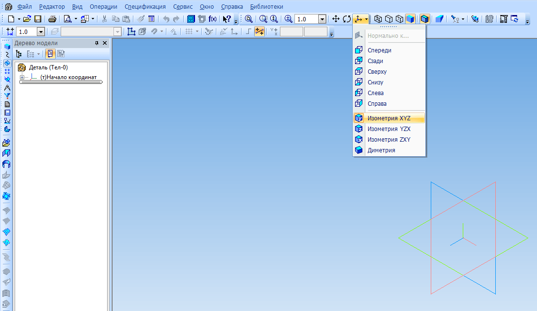
Set Orientation XYZ isometry.
Select a plane to create the first sketch ZXAnd click on the toolbar Current state. Create a sketch as shown in the image below. Apply dimensions.

Extrude the sketch in the forward direction by 10 mm.

XY.

Extrude it from the middle plane by 50 mm.

Create the following sketch on a plane XY.
Extrude it from the middle plane by 35 mm.

Select the specified surface and create a sketch on it.


Extrude cut in a straight line through everything.

On the indicated surface, sketch the hole.


Create a hole with the command Extrude cut.

Create a sketch for the last element on the plane XY.

Execute the command Cut extrusion in two directions. Through everything in every direction.

And so the detail is ready. But for now, there is still no way to show it in isometry with a one-quarter cutout. To do this, we will create a new version of the part. What are performances and why they are used, I told in one of the last lessons. Before the advent of versions in Compass-3D, in order to show isometry with a cutout in a drawing, you had to create a copy of the model, make a cutout in the copy and create a view from it, which is not very convenient. Now you can do without it. So, open Document Manager and create a dependent execution. Make it current and click OK.

Create a sketch on the ZX plane.

Complete Section by sketch in the opposite direction.

Execution is ready. The current performance can be changed in the window on the panel Current state.

Create a new drawing. IN Document Manager set A3 format, horizontal orientation. Click the button Standard Views on the toolbar Kinds. In the opening window, select the saved model. Please note that the window Execution must be empty, which means that the views will be created from the base execution. Set the Main View Orientation to Front.

Specify an anchor point for the view. After that, you need to create a view from execution. On panel Kinds press the button Arbitrary View. In the window Execution select variant -01, select main view orientation Isometric XYZ

It remains only to apply hatching, dimensions and create the necessary cuts, in accordance with the scheme in the task.

P.S. For those who want to become a KOMPAS-3D Master! The new training video course will allow you to easily and quickly master the KOMPAS-3D system from scratch to the level of an experienced user.
Rectangular isometry called an axonometric projection, in which the coefficients of distortion along all three axes are equal, and the angles between the axonometric axes are 120. On fig. 1 shows the position of the axonometric axes of rectangular isometry and methods for constructing them.
Rice. 1. Construction of axonometric axes of rectangular isometry using: a) segments; b) compass; c) squares or a protractor.
In practical constructions, the distortion coefficient (K) along the axonometric axes according to GOST 2.317-2011 is recommended to be equal to one. In this case, the image is obtained larger than the theoretical or exact image at distortion factors of 0.82. The magnification is 1.22. On fig. 2 shows an example of a part image in a rectangular isometric projection.

Rice. 2. Isometric detail.
Construction in isometry of flat figures
A regular hexagon ABCDEF is given, located parallel to the horizontal projection plane H (P 1).
a) We build isometric axes (Fig. 3).
b) The coefficient of distortion along the axes in isometry is equal to 1, therefore, from the point O 0 along the axes, we set aside the natural values of the segments: A 0 O 0 \u003d AO; О 0 D 0 = ОD; K 0 O 0 \u003d KO; O 0 P 0 \u003d OR.
c) Lines parallel to the coordinate axes are also drawn in isometry parallel to the corresponding isometric axes in full size.
In our example, the sides BC and FE parallel to the axis X.
In isometry, they are also drawn parallel to the X axis in full size B 0 C 0 \u003d BC; F 0 E 0 = FE.
d) Connecting the obtained points, we obtain an isometric image of a hexagon in the H (P 1) plane.

Rice. 3. Isometric projection of a hexagon in the drawing
and in the horizontal projection plane
On fig. 4 shows the projections of the most common flat figures in various projection planes.
The most common shape is the circle. The isometric projection of a circle is generally an ellipse. An ellipse is built by points and traced along a pattern, which is very inconvenient in drawing practice. Therefore, ellipses are replaced by ovals.
On fig. 5 built in isometric cube with circles inscribed in each face of the cube. With isometric constructions, it is important to correctly position the axes of the ovals depending on the plane in which the circle is supposed to be drawn. As seen in fig. 5, the major axes of the ovals are located along the larger diagonal of the rhombuses into which the faces of the cube are projected.

Rice. 4 Isometric image flat figures
a) on the drawing; b) on the H plane; c) on the plane V; d) on the plane W.
For rectangular axonometry of any kind, the rule for determining the main axes of an oval ellipse into which a circle is projected, lying in any projection plane, can be formulated as follows: the major axis of the oval is perpendicular to the axonometric axis that is absent in this plane, and the minor one coincides with the direction of this axis. The shape and size of the ovals in each plane of isometric projections are the same.


In many cases, when performing technical drawings, it turns out to be useful along with the image of objects in the system. orthogonal projections have clearer images. To construct such images, projections are used, called axonometric .
The method of axonometric projection is that the given object, together with the axes rectangular coordinates, to which this system belongs in space, is projected in parallel onto some plane α (Figure 4.1).
Figure 4.1
Projection direction S determines the position of the axonometric axes on the projection plane α , as well as their distortion coefficients. At the same time, it is necessary to ensure the clarity of the image and the ability to determine the positions and sizes of the object.
As an example, Figure 4.2 shows the construction of an axonometric projection of a point A by its orthogonal projections.

Figure 4.2
Here in letters k, m, n the distortion coefficients along the axes OX, OY And oz respectively. If all three coefficients are equal to each other, then the axonometric projection is called isometric , if only two coefficients are equal, then the projection is called dimetric , if k≠m≠n , then the projection is called trimetric .
If the projection direction S perpendicular to the projection plane α , then the axonometric projection is called rectangular . Otherwise, the axonometric projection is called oblique .
GOST 2.317-2011 establishes the following rectangular and oblique axonometric projections:
- rectangular isometric and dimetric;
- oblique frontally isometric, horizontally isometric and frontally dimetric;
Below are the parameters of only the three most commonly used axonometric projections in practice.
Each such projection is determined by the position of the axes, the coefficients of distortion along them, the sizes and directions of the axes of ellipses located in planes parallel to the coordinate planes. To simplify geometric constructions, the distortion coefficients along the axes, as a rule, are rounded off.
4.1. Rectangular projections
4.1.1. Isometric projection
The direction of the axonometric axes is shown in Figure 4.3.

Figure 4.3 - Axonometric axes in a rectangular isometric projection
Actual distortion coefficients along the axes OX, OY And oz equal 0,82 . But it is not convenient to work with such values of distortion coefficients, therefore, in practice, reduced distortion coefficients. This projection is usually performed without distortion, therefore, the given distortion coefficients are taken k=m=n=1 . Circles lying in planes parallel to the projection planes are projected into ellipses, the major axis of which is equal to 1,22 , and the small 0,71 generating circle diameter D.
The major axes of ellipses 1, 2 and 3 are at 90º to the axes OY, oz And OX, respectively.
An example of an isometric projection of a conditional part with a cutout is shown in Figure 4.4.

Figure 4.4 - Image of a part in a rectangular isometric projection
4.1.2. Dimetric projection
The position of the axonometric axes is shown in Figure 4.5.
To construct an angle approximately equal to 7º10´, under construction right triangle, whose legs are one and eight units of length; to construct an angle approximately equal to 41º25´- the legs of the triangle, respectively, are equal to seven and eight units of length.
Distortion coefficients along the OX and OZ axes k=n=0.94 and along the OY axis - m=0.47. When rounding these parameters, it is assumed k=n=1 And m=0.5. In this case, the dimensions of the axes of the ellipses will be: the major axis of the ellipse 1 is equal to 0.95D and ellipses 2 and 3 - 0.35D(D is the diameter of the circle). In Figure 4.5, the major axes of ellipses 1, 2, and 3 are angled 90º to the OY, OZ and OX axes, respectively.
An example of a rectangular dimetric projection of a conditional part with a cutout is shown in Figure 4.6.
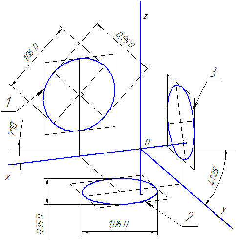
Figure 4.5 - Axonometric axes in a rectangular dimetric projection

Figure 4.6 - Image of a part in a rectangular dimetric projection
4.2 Oblique projections
4.2.1 Frontal dimetric projection
The position of the axonometric axes is shown in Figure 4.7. It is allowed to use frontal dimetric projections with an angle of inclination to the OY axis equal to 30 0 and 60 0 .
The coefficient of distortion along the OY axis is equal to m=0.5 and along the axes OX and OZ - k=n=1.
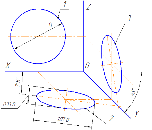
Figure 4.7 - Axonometric axes in oblique frontal dimetric projection
Circles lying in planes parallel to the frontal projection plane are projected onto the XOZ plane without distortion. Major axes of ellipses 2 and 3 are equal 1.07D, and the minor axis is 0.33D(D is the diameter of the circle). The major axis of the ellipse 2 makes an angle with the OX axis 7º 14´, and the major axis of the ellipse 3 makes the same angle with the OZ axis.
An example of an axonometric projection of a conditional part with a cutout is shown in Figure 4.8.
As can be seen from the figure, this part is located in such a way that its circles are projected onto the XOZ plane without distortion.
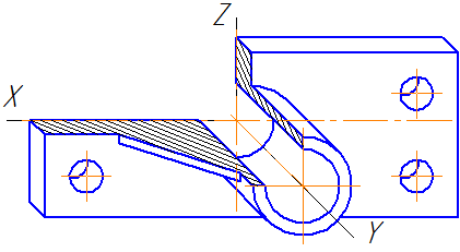
Figure 4.8 - Image of a part in an oblique frontal dimetric projection
4.3 Building an ellipse
4.3.1 Building an ellipse along two axes
On these axes of the ellipse AB and CD, two concentric circles are built as on diameters (Figure 4.9, a).
One of these circles is divided into several equal (or unequal) parts.
Radii are drawn through the division points and the center of the ellipse, which also divide the second circle. Then straight lines parallel to the lines AB are drawn through the division points of the great circle.
The intersection points of the corresponding lines will be the points belonging to the ellipse. Figure 4.9, a shows only one desired point 1.

a B C
Figure 4.9 - Construction of an ellipse along two axes (a), along chords (b)
4.3.2 Building an ellipse from chords
The diameter of the circle AB is divided into several equal parts, in Figure 4.9, b there are 4 of them. Through points 1-3, chords are drawn parallel to the diameter CD. In any axonometric projection (for example, in an oblique dimetric projection), the same diameters are depicted, taking into account the distortion coefficient. So in Figure 4.9,b A 1 B 1 \u003d AB And C 1 D 1 \u003d 0.5CD. The diameter A 1 B 1 is divided into the same number of equal parts as the diameter AB, through the obtained points 1-3, segments are drawn equal to the corresponding chords multiplied by the distortion factor (in our case, 0.5).
4.4 Cross-hatching
The hatching lines of sections (sections) in axonometric projections are drawn parallel to one of the diagonals of the squares lying in the corresponding coordinate planes, the sides of which are parallel to the axonometric axes (Figure 4.10: a - hatching in rectangular isometry; b - hatching in oblique frontal dimetry).
a b
Figure 4.10 - Examples of hatching in axonometric projections
As already discussed, the isometric projection axes are located at an angle of 120 ° to each other.
They can be built in several ways.
A. With the help of a compass. Initially, an axis is drawn and the point of intersection of the axes is chosen on it ABOUT. From a point ABOUT with any radius, draw an arc intersecting the axis at the point 1. From it, with the same radius on the arc, serifs are made at points 3 , 4 , through which the axes are drawn (Fig. 2.48).
B. The construction of axes using a ruler and a square with angles of 30°, 60° and 90° is shown in fig. 2.49. axes hiu carried out at an angle of 30 ° to the horizontal line.

ISOMETRIC PROJECTIONS OF POLYGONS
The construction of an isometric projection of objects usually begins with the image of some of its faces, which are based on flat figures. Consider the construction of some polygons by given rectangular projections.
For all constructions, the x and axes are initially drawn at on rectangular projections and the corresponding axes in isometric projection, i.e. produce alignment of rectangular and axonometric axes.
A. Construction of a triangle located in a horizontal plane (Fig. 2.50). from point ABOUT lay along the x-axis segments equal to half the side of the triangle, and along the x-axis y - its height AND. The resulting points are connected by straight lines.
Similarly, triangles are built located in the frontal and profile planes (Fig. 2.51).
B. Construction of a square located in a horizontal plane (Fig. 2.52). Draw a line along the x-axis A, equal to the side of the square, along the axis y - line segment b, from the points obtained, segments are drawn parallel to the x and axes y.


B. Construction of a hexagon located in a horizontal plane (Fig. 2.53).
Construction of hexagons in planes p 2 And p 3 shown in fig. 2.53, b.
To construct a hexagon, it is advisable to choose the isometric projection axes so that they pass through the center of the hexagon. On the x-axis to the right and left of the point ABOUT lay off cuts equal side hexagon. Along the y axis, symmetrical to a point ABOUT lay off segments equal to half the distance h between opposite sides.
From points received on the axis y, draw to the right and left parallel to the x axis segments equal to half the side of the hexagon. The resulting points are connected by straight lines.

When constructing the contours of complex, asymmetrical figures (Fig. 2.54), their vertices are 7, 2, ..., 7 are found by measuring the markings x p x 2, x 3, x 4, x 5 on a rectangular projection, and transferring them to the axes or straight lines parallel to this axis of the isometric projection. Do the same with sizes. at R y 2 , y y 4 . At the intersection of the corresponding lines, the vertices of a given flat figure are found and connected to each other.

Questions and tasks
- 1. In what sequence is the construction of a triangle performed in an isometric projection? Any flat figure?
- 2. From the task book, complete one of the options for task No. 32. In it, it is necessary to build isometric projections of “flat” figures in the frontal and profile planes of the projections.