
How to draw a cube in isometric view. Building an axonometric image of a part
In this tutorial, I will show you how to place an isometric view of a model with a front quarter cutout on a drawing. I will show how this is done using an example of a task taken from study guide S.K. Bogolyubov "Individual assignments for the course of drawing". The task is as follows: according to these two projections, build a third projection using the cuts indicated in the diagram, an isometric projection of the training model with a cutout of the front quarter.
Let's start creating a model. Create a new part by executing the command File - Create.
Give it a name. To do this, run the command File - Model Properties. On the tab Property List in the column Name enter Rack.

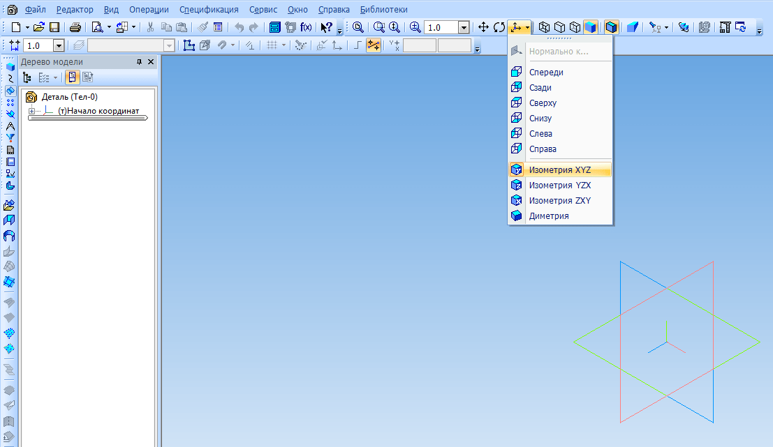
Set Orientation XYZ isometry.
Select a plane to create the first sketch ZXAnd click on the toolbar Current state. Create a sketch as shown in the image below. Apply dimensions.

Extrude the sketch in the forward direction by 10 mm.

XY.

Extrude it from the middle plane by 50 mm.

Create the following sketch on a plane XY.
Extrude it from the middle plane by 35 mm.

Select the specified surface and create a sketch on it.


Extrude cut in a straight line through everything.

On the indicated surface, sketch the hole.


Create a hole with the command Extrude cut.

Create a sketch for the last element on the plane XY.

Execute the command Cut extrusion in two directions. Through everything in every direction.

And so the detail is ready. But for now, there is still no way to show it in isometry with a one-quarter cutout. To do this, we will create a new version of the part. What are performances and why they are used, I told in one of the last lessons. Before the advent of versions in Compass-3D, in order to show isometry with a cutout in a drawing, you had to create a copy of the model, make a cutout in the copy and create a view from it, which is not very convenient. Now you can do without it. So, open Document Manager and create a dependent execution. Make it current and click OK.

Create a sketch on the ZX plane.

Complete Section by sketch in the opposite direction.

Execution is ready. The current performance can be changed in the window on the panel Current state.

Create a new drawing. IN Document Manager set A3 format, horizontal orientation. Click the button Standard Views on the toolbar Kinds. In the opening window, select the saved model. Please note that the window Execution must be empty, which means that the views will be created from the base execution. Set the Main View Orientation to Front.

Specify an anchor point for the view. After that, you need to create a view from execution. On panel Kinds press the button Arbitrary View. In the window Execution select variant -01, select main view orientation Isometric XYZ

It remains only to apply hatching, dimensions and create the necessary cuts, in accordance with the scheme in the task.

P.S. For those who want to become a KOMPAS-3D Master! The new training video course will allow you to easily and quickly master the KOMPAS-3D system from scratch to the level of an experienced user.
For execution isometric view of any part, you need to know the rules for constructing isometric projections of flat and volume geometric shapes.
Rules for constructing isometric projections of geometric shapes. The construction of any flat figure should begin with the axes of isometric projections.
When constructing an isometric projection of a square (Fig. 109), from the point O along the axonometric axes, half the length of the side of the square is laid in both directions. Through the resulting serifs, straight lines are drawn parallel to the axes.
When constructing an isometric projection of a triangle (Fig. 110), segments equal to half the side of the triangle are laid along the X axis from point 0 to both sides. On the Y-axis from the point O, the height of the triangle is plotted. Connect the resulting serifs with straight line segments.
Rice. 109. Rectangular and isometric projections of a square

Rice. 110. Rectangular and isometric projections of a triangle
When constructing an isometric projection of a hexagon (Fig. 111), from the point O, along one of the axes, lay off (in both directions) the radius of the circumscribed circle, and along the other - H / 2. Through the obtained serifs, straight lines are drawn parallel to one of the axes, and the length of the side of the hexagon is laid on them. Connect the resulting serifs with straight line segments.

Rice. 111. Rectangular and isometric projections of a hexagon

Rice. 112. Rectangular and isometric projections of a circle
When constructing an isometric projection of a circle (Fig. 112), segments equal to its radius are plotted along the coordinate axes from the point O. Through the resulting serifs, straight lines are drawn parallel to the axes, obtaining an axonometric projection of the square. From vertices 1, 3, arcs CD and KL are drawn with a radius of 3C. Connect points 2 with 4, 3 with C and 3 with D. At the intersections of straight lines, the centers a and b of small arcs are obtained, after drawing which they get an oval that replaces the axonometric projection of the circle.
Using the described constructions, it is possible to perform axonometric projections of simple geometric bodies (Table 10).
10. Isometric projections of simple geometric bodies


Methods for constructing an isometric projection of a part:
1. The method of constructing an isometric projection of a part from a shaping face is used for parts whose shape has a flat face, called a shaping face; the width (thickness) of the part is the same throughout, there are no grooves, holes and other elements on the side surfaces. The sequence for constructing an isometric projection is as follows:
1) construction of isometric projection axes;
2) construction of an isometric projection of the shaping face;
3) construction of projections of the remaining faces by means of the image of the edges of the model;

Rice. 113. Building an isometric projection of a part, starting from a shaping face
4) stroke of the isometric projection (Fig. 113).
- The method of constructing an isometric projection based on the sequential removal of volumes is used in cases where the displayed form is obtained as a result of the removal of any volumes from the original form (Fig. 114).
- The method of constructing an isometric projection based on a sequential increment (adding) of volumes is used to perform an isometric image of a part, the shape of which is obtained from several volumes connected in a certain way to each other (Fig. 115).
- Combined method of constructing an isometric projection. An isometric view of a part whose shape is obtained as a result of a combination various ways shaping is performed using a combined construction method (Fig. 116).
An axonometric projection of a part can be performed with an image (Fig. 117, a) and without an image (Fig. 117, b) of invisible parts of the form.

Rice. 114. Construction of an isometric projection of a part based on sequential removal of volumes

Rice. 115 Construction of an isometric projection of a part based on a sequential increment of volumes

Rice. 116. Using a combined method of constructing an isometric projection of a part

Rice. 117. Variants of the image of isometric projections of the part: a - with the image of invisible parts;
b - without the image of invisible parts
In isometric projection, all coefficients are equal to each other:
k = t = n;
3 to 2 = 2,
k = yj 2UZ - 0.82.
Therefore, when constructing an isometric projection, the dimensions of the object, plotted along the axonometric axes, are multiplied by 0.82. Such recalculation of sizes is inconvenient. Therefore, for simplicity, an isometric projection is usually performed without reducing the size (distortion) along the axes x, y, i, those. take the reduced distortion coefficient equal to unity. The resulting image of the object in isometric projection has several big sizes than in reality. The increase in this case is 22% (expressed as the number 1.22 = 1: 0.82).
Each segment directed along the axes x, y, z or parallel to them, retains its magnitude.
The location of the isometric projection axes is shown in fig. 6.4. On fig. 6.5 and 6.6 show orthogonal (A) and isometric (b) point projection A and segment L IN.
Hexagonal prism in isometry. Construction of a hexagonal prism according to a given drawing in the system orthogonal projections(on the left in fig. 6.7) is shown in fig. 6.7. On the isometric axis I put off height H, draw lines parallel to the axes hiu. Mark on a line parallel to the axis X, position of points / and 4.
To build a point 2 determine the coordinates of this point in the drawing - x 2 And at 2 and, setting aside these coordinates on the axonometric image, build a point 2. Points are built in the same way. 3, 5 And 6.
The constructed points of the upper base are connected to each other, an edge is drawn from the point / to the intersection with the x-axis, then -
dotted edges 2 , 3, 6. The ribs of the lower base are drawn parallel to the ribs of the upper one. Building a point L, located on the side face, along the coordinates x A(or at A) And 1 A evident from

Circle isometry. Circles in isometry are depicted as ellipses (Fig. 6.8) indicating the values of the axes of the ellipses for the reduced distortion coefficients equal to one.
The major axis of the ellipses is at 90° for ellipses lying IN THE PLANE xC>1 to OSI y, IN THE PLANE y01 TO X-AXIS, in plane hoy To OSI?

When constructing an isometric image by hand (like a drawing), an ellipse is performed at eight points. For example, trays 1, 2, 3, 4, 5, 6, 7 and 8 (see figure 6.8). points 1, 2, 3 and 4 are found on the corresponding axonometric axes, and the points 5, 6, 7 And 8 are built according to the values of the corresponding major and minor axes of the ellipse. When drawing ellipses in isometric projection, you can replace them with ovals and build them as follows 1 . The construction is shown in fig. 6.8 on the example of an ellipse lying in a plane xOz. From the point / as from the center, make a notch with a radius R=D on the continuation of the minor axis of the ellipse at the point O, (they also build a point symmetrical to it in the same way, which is not shown in the drawing). From point O, how to draw an arc from the center CGC radius D, which is one of the arcs that make up the contour of the ellipse. From point O, as from the center, an arc of radius is drawn O^G to the intersection with the major axis of the ellipse at points OU Passing through the points O p 0 3 straight line, found at the intersection with the arc CGC point TO, which defines 0 3 K- the value of the radius of the closing arc of the oval. points TO are also the conjugation points of the arcs that make up the oval.
Cylinder isometric. The isometric image of a cylinder is determined by the isometric images of the circles of its base. Construction in isometry of a cylinder with a height H according to the orthogonal drawing (Fig. 6.9, left) and the point C on its side surface is shown in fig. 6.9, right.

Suggested by Yu.B. Ivanov.
An example of construction in an isometric projection of a round flange with four cylindrical holes and one triangular one is shown in fig. 6.10. When constructing the axes of cylindrical holes, as well as the edges of a triangular hole, their coordinates were used, for example, the coordinates x 0 and y 0 .

Consider fig. 92. It shows the frontal dimetric projection of a cube with circles inscribed in its faces.
Circles located on planes perpendicular to the x and z axes are depicted as ellipses. The front face of the cube, perpendicular to the y-axis, is projected without distortion, and the circle located on it is depicted without distortion, that is, it is described by a compass. Therefore, the frontal dimetric projection is convenient for depicting objects with curvilinear outlines, such as those shown in Fig. 93.

Construction of a frontal dimetric projection of a flat part with a cylindrical hole. Frontal dimetric projection of a flat part with a cylindrical hole is performed as follows.
1. Build the outlines of the front face of the part using a compass (Fig. 94, a).
2. Straight lines are drawn through the centers of the circle and arcs parallel to the y-axis, on which half the thickness of the part is laid. Get the centers of the circle and arcs located on the back surface of the part (Fig. 94, b). From these centers, a circle and arcs are drawn, the radii of which must be equal to the radii of the circle and arcs of the front face.

3. Draw tangents to arcs. Remove extra lines and outline the visible contour (Fig. 94, c).
Isometric projections of circles. A square in isometric projection is projected into a rhombus. Circles inscribed in squares, for example, located on the faces of a cube (Fig. 95), are depicted in isometric projection as ellipses. In practice, ellipses are replaced by ovals, which are drawn with four arcs of circles.

Construction of an oval inscribed in a rhombus.
1. Build a rhombus with a side equal to the diameter of the depicted circle (Fig. 96, a). To do this, isometric axes x and y are drawn through the point O, and segments equal to the radius of the depicted circle are plotted on them from the point O. Through points a, w, c and d draw straight lines parallel to the axes; get a rhombus. The major axis of the oval is located on the major diagonal of the rhombus.
2. Fit into a rhombus oval. To do this, from the vertices of obtuse angles (points A and B) describe arcs with a radius R equal to the distance from the vertex of an obtuse angle (points A and B) to points a, b or c, d, respectively. Straight lines are drawn through points B and a, B and b (Fig. 96, b); the intersection of these lines with the larger diagonal of the rhombus gives points C and D, which will be the centers of small arcs; the radius R 1 of small arcs is Ca (Db). The arcs of this radius match the large arcs of the oval. This is how an oval is built, lying in a plane perpendicular to the z axis (oval 1 in Fig. 95). Ovals located in planes perpendicular to the axes x (oval 3) and y (oval 2) are built in the same way as oval 1., only the construction of oval 3 is carried out on the axes y and z (Fig. 97, a), and the oval 2 (see Fig. 95) - on the x and z axes (Fig. 97, b).


Construction of an isometric projection of a part with a cylindrical hole.
How to apply the considered constructions in practice?
An isometric projection of the part is given (Fig. 98, a). It is necessary to depict a through cylindrical hole drilled perpendicular to the front face.
Constructions are performed as follows.
1. Find the position of the center of the hole on the front face of the part. Isometric axes are drawn through the found center. (To determine their direction, it is convenient to use the image of a cube in Fig. 95.) Segments equal to the radius of the depicted circle are plotted on the axes from the center (Fig. 98, a).
2. Build a rhombus, the side of which is equal to the diameter of the circle being depicted; spend a large diagonal of the rhombus (Fig. 98, b).
3. Describe large arcs of an oval; find centers for small arcs (Fig. 98, c).
4. Carry out small arcs (Fig. 98, d).
5. Build the same oval on the back face of the part and draw tangents to both ovals (Fig. 98, e).

Answer the questions

1. What figures are depicted in the frontal dimetric projection of circles located on planes perpendicular to the x and y axes?
2. Is a circle distorted in frontal dimetric projection if its plane is perpendicular to the y-axis?
3. When depicting what details is it convenient to use frontal dimetric projection?
4. What figures are depicted in an isometric projection of circles located on planes perpendicular to the axes x, y, z?
5. What figures in practice replace ellipses depicting circles in isometric projection?
6. What elements does the oval consist of?
7. What are the diameters of the circles depicted by ovals inscribed in rhombuses in fig. 95 if the sides of these rhombuses are 40 mm?
Assignments to § 13 and 14
Exercise 42

On fig. 99, axes are drawn to build three rhombuses depicting squares in isometric projection. Consider fig. 95 and write down on which side of the cube - the top, right side or left side each rhombus will be located, built on the axes given in fig. 99. Which axis (x, y or z) will be perpendicular to the plane of each rhombus?
Theoretical part
For a visual representation of products or their components, axonometric projections are used. In this paper, we consider the rules for constructing a rectangular isometric projection.
For rectangular projections, when the angle between the projecting rays and the axonometric projection plane is 90°, the distortion coefficients are related by the following relationship:
k 2 + t 2 + p 2 = 2. (1)
For isometric projection, the distortion coefficients are equal, therefore, k = t = n.
From formula (1) it turns out
3k2 =2; ; k = t = P  0,82.
0,82.
The fractional nature of the distortion coefficients complicates the calculations of the dimensions required when constructing an axonometric image. To simplify these calculations, the following distortion factors are used:
for isometric projection, the distortion coefficients are:
k = t = n = 1.
When using the given distortion coefficients, the axonometric image of an object is obtained 1.22 times larger than its natural size for an isometric projection. the scale of the image is: for isometry - 1.22: 1.
The layouts of the axes and the values of the reduced distortion coefficients for the isometric projection are shown in fig. 1. The values of the slopes are also indicated there, which can be used to determine the direction of the axonometric axes in the absence of an appropriate tool (protractor or square with an angle of 30 °).

Circles in axonometry, in general case, are projected as ellipses, and when using real distortion coefficients, the major axis of the ellipse is equal in magnitude to the diameter of the circle. When using the given distortion coefficients, the linear quantities are enlarged, and in order to bring all the elements of the part depicted in axonometry to the same scale, the major axis of the ellipse for isometric projection is assumed to be 1.22 of the diameter of the circle.
The minor axis of the ellipse in isometry for all three projection planes is equal to 0.71 of the circle diameter (Fig. 2).

Great importance for the correct image of the axonometric projection of the object, it has the location of the axes of the ellipses relative to the axonometric axes. In all three planes of a rectangular isometric projection the major axis of the ellipse must be directed perpendicular to an axis that is absent in the given plane. For example, for an ellipse located in the plane xОz, the major axis is directed perpendicular to the axis y, projected onto a plane xОz exactly; an ellipse in a plane yOz, - perpendicular to the axis X etc. In fig. 2 shows the arrangement of ellipses in different planes for isometric projection. The distortion coefficients for the axes of the ellipses are also given here, the values of the axes of the ellipses are indicated in brackets when using real coefficients.
In practice, the construction of ellipses is replaced by the construction of four-center ovals. On fig. 3 shows the construction of an oval in the plane P 1. The major axis of the ellipse AB is directed perpendicular to the missing axis z, and the minor axis of the ellipse CD coincides with it. From the point of intersection of the axes of the ellipse, a circle is drawn with a radius equal to the radius of the circle. On the continuation of the minor axis of the ellipse, the first two centers of the conjugation arcs (O 1 and O 2) are found, of which the radius R 1 \u003d O 1 1 \u003d O 2 2 draw circular arcs. At the intersection of the major axis of the ellipse with the lines of radius R1 determine the centers (O 3 and O 4), of which the radius R 2 \u003d O 3 1 \u003d O 4 4 conduct closing arcs of conjugation.

Usually, an axonometric projection of an object is built according to an orthogonal drawing, and the construction is simpler if the position of the part relative to the coordinate axes X,at And z remains the same as in the orthogonal drawing. main view object should be placed on a plane xОz.
The construction begins with the drawing of axonometric axes and the image of a flat figure of the base, then the main contours of the part are built, lines of ledges, recesses are applied, holes are made in the part.
When depicting axonometric sections on axonometric projections, as a rule, the invisible outline is not shown with dashed lines. To identify inner contour details, as well as in an orthogonal drawing, in axonometry make cuts, but these cuts may not repeat the cuts of an orthogonal drawing. Most often, on axonometric projections, when the part is a symmetrical figure, one fourth or one eighth of the part is cut out. On axonometric projections, as a rule, full sections are not used, since such sections reduce the clarity of the image.
When performing axonometric images with cuts, the hatching lines of the sections are applied parallel to one of the diagonals of the projections of squares lying in the corresponding coordinate planes, the sides of which are parallel to the axonometric axes (Fig. 4).

When making cuts, the secant planes guide only in parallel coordinate planes (xОz, yОz or hoy).
Methods for constructing an isometric projection of a part: 1. The method for constructing an isometric projection of a part from a shaping face is used for parts whose shape has a flat face, called a shaping face; the width (thickness) of the part is the same throughout, there are no grooves, holes and other elements on the side surfaces. The sequence of isometric projection construction is as follows: 1) construction of isometric projection axes; 2) construction of an isometric projection of the shaping face; 3) construction of projections of the remaining faces by means of the image of the edges of the model; 4) stroke of the isometric projection (Fig. 5).  Rice. 5. Construction of an isometric projection of a part, starting from the shaping face 2. The method of constructing an isometric projection based on the sequential removal of volumes is used in cases where the displayed form is obtained by removing any volumes from the original form (Fig. 6). 3. The method of constructing an isometric projection based on a sequential increment (adding) of volumes is used to perform an isometric image of a part, the shape of which is obtained from several volumes connected in a certain way to each other (Fig. 7). 4. Combined method of constructing an isometric projection. An isometric projection of a part, the shape of which was obtained as a result of a combination of various shaping methods, is performed using a combined construction method (Fig. 8). The axonometric projection of the part can be performed with the image (Fig. 9, a) and without the image (Fig. 9, b) of the invisible parts of the form. Rice. 5. Construction of an isometric projection of a part, starting from the shaping face 2. The method of constructing an isometric projection based on the sequential removal of volumes is used in cases where the displayed form is obtained by removing any volumes from the original form (Fig. 6). 3. The method of constructing an isometric projection based on a sequential increment (adding) of volumes is used to perform an isometric image of a part, the shape of which is obtained from several volumes connected in a certain way to each other (Fig. 7). 4. Combined method of constructing an isometric projection. An isometric projection of a part, the shape of which was obtained as a result of a combination of various shaping methods, is performed using a combined construction method (Fig. 8). The axonometric projection of the part can be performed with the image (Fig. 9, a) and without the image (Fig. 9, b) of the invisible parts of the form.  Rice. 6. Construction of an isometric projection of a part based on sequential removal of volumes Rice. 6. Construction of an isometric projection of a part based on sequential removal of volumes  Rice. 7 Building an isometric projection of a part based on a sequential increase in volumes Rice. 7 Building an isometric projection of a part based on a sequential increase in volumes  Rice. 8. Using the combined method of constructing an isometric projection of a part Rice. 8. Using the combined method of constructing an isometric projection of a part  Rice. 9. Variants of the image of isometric projections of the part: a - with the image of invisible parts; b - without the image of invisible parts Rice. 9. Variants of the image of isometric projections of the part: a - with the image of invisible parts; b - without the image of invisible parts |
EXAMPLE OF PERFORMING THE TASK ON AXONOMETRY

Construct a rectangular isometry of the part according to the completed drawing of a simple or complex section at the student's choice. The part is built without invisible parts with a ¼ part cut along the axes.
The figure shows the design of a drawing of an axonometric projection of a part after removing unnecessary lines, tracing the contours of the part and hatching the sections.
TASK №5 ASSEMBLY DRAWING OF THE VALVE