
Do-it-yourself digital television antenna hdtv indoor. How to make a digital TV antenna with your own hands for a summer residence and at home
Digital terrestrial television (DVB-Digital Video Broadcasting) is a technology for transmitting television images and sound using digital coding of video and sound. Digital coding, in contrast to analog, ensures signal delivery with minimal losses, since the signal is not affected by external interference. At the time of this writing, 20 digital channels are available, in the future this number should increase. This number of digital channels is not available in all regions, find out more precisely about the ability to catch digital channels you can visit the website www.rtrs.rf. If there are digital channels in your area, then it remains to make sure that your TV supports DVB-T2 technology (this can be found in the documentation for the TV) or buy a DVB-T2 set-top box and connect the antenna. The question arises - Which antenna to use for digital television? or How to make an antenna for digital TV? In this article, I would like to dwell in more detail on antennas for watching digital television, and in particular, I will show how to make an antenna for digital television yourself.
The first thing I would like to emphasize is that a specialized antenna is not needed for digital television, an analog antenna (the one you used earlier to watch analog channels) is quite suitable. Moreover, only tv cable...
In my opinion, the simplest antenna for digital television is a television cable. Everything is extremely simple, a coaxial cable is taken, an F connector and an adapter for connecting to a TV are put on one end, and the central core of the cable (a kind of whip antenna) is exposed at the other end. It remains only to decide how many centimeters to expose the central core, since the quality of reception of digital channels depends on this. To do this, you need to understand at what frequency digital channels broadcast in your region, for this go to the website www.rtrs.rf / when / here on the map find the tower closest to you and see how often digital channels broadcast.
More detailed information you will get it if you click the "Details" button.
Now you need to calculate the wavelength. The formula is quite simple:
where, λ (lambda) is the wavelength,
c - speed of light (3-10 8 m / s)
F - frequency in hertz
or easier λ = 300 / F (MHz)
In my case, the frequency is 602 MHz and 610 MHz, for the calculation I will use the frequency of 602 MHz
Total: 300/602 ≈ 0.5 m = 50 cm.
Leave half a meter central vein coaxial cable it is not beautiful and inconvenient, so I will leave half, maybe a quarter of the wavelength.
l = λ * k / 2
where l is the length of the antenna (central core)
λ- wavelength (calculated earlier)
k is the shortening factor, since the length of the entire cable will not be large, this value can be considered equal to 1.
As a result, l = 50/2 = 25 cm.
From these calculations, it turned out that for a frequency of 602 MHz I need to strip 25 cm of the coaxial cable.
Here is the result of the work done

This is how the antenna looks when installed.

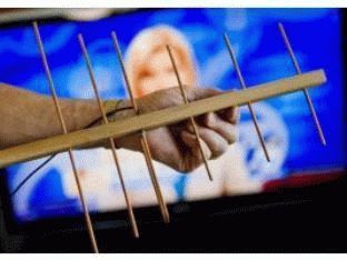
Aerial view while watching TV.

Currently in Moscow digital terrestrial DVB-T2 broadcasting is carried out on the following channels: 30 (multiplex 1), 24 (multiplex 2), 34 (multiplex 3. It is in testing mode, some TV channels have not been finally determined) of the UHF range (see the frequency grid).
Since January 2015, the third multiplex has been launched in Moscow and the Moscow Region(!) on channel 34, the programs of which are now being selected on a tender basis. Permanent programs of the 3 multiplexes are: Match! Arena, Music of the First and Life news... The list of programs participating in the tender can be viewed.
(!) On channel 58 (770 MHz), test broadcasting of an ultra-high definition signal (Ultra HD 4K) has been carried out since October 2016. The signal can be received by any resident of Moscow and the nearest Moscow region if there is a TV with support for Ultra HD / DVB-T2 / HEVC.
| Multiplex 1 | Multiplex 2 | Multiplex 3 | ||
| channel 30 (546 MHz) | channel 24 (498 MHz) | channel 34 (578 MHz) | ||
| Programs | Programs | Programs | ||
| 1 channel | Ren TV | Match! Arena | ||
| Russia 1 | Saved | My Planet Science 2.0 Fight club |
||
| Match! | STS | History, Cartoon, Russian detective, Russian bestseller |
||
| NTV | Home | Country, Sundress | ||
| 5 (Peter) | TV 3 | Mom, 24_DOC, Amusement Park IQ HD |
||
| Russia K | Friday | Euronews, Trust | ||
| Russia 24 | Star | Music of the First | ||
| Carousel | Peace | A Minor, Kitchen TV, Auto Plus, India TV; HD Life, STV |
||
| OTP | TNT | LifeNews | ||
| TVC | Muz TV | Our football (temporarily coded) |
You can choose the type of receiver.
A device for the most accurate tuning of digital terrestrial (DVB-T / T2) antennas.
Long Range Antennas DVB-T2
Balcony antennas DVB-T2
| AURA | ||
 |
Compact antenna for receiving television signals in the UHF range with a built-in LTE filter(above 790 MHz). Helps to avoid negative impact network interference cellular LTE / 4G to the receiving equipment and provide a more uniform frequency response in the operating frequency range of the UHF. Horizontal polarization. Minimal packaging volume and easy tool-free assembly. It is widely used for installation on a balcony in apartments for broadcasting digital terrestrial television of the DVB-T2 standard. | |
| Price: 29 € | ||
 |
Compact antenna with built-in amplifier +5 V... Designed to receive television signals in the UHF range. It is easily installed on the wall (using a bracket) or directly on the balcony grill in apartments for broadcasting digital terrestrial television of the DVB-T2 standard. |
Please understand those who want to tune the antenna to television: nature has not created digital gizmos. There are analog signals in the Universe, the power changes according to the quantum states of electrons. The transitions are so small that they seem continuous to a person. The signal can be represented by a certain number multiplied by elemental energy. We want to make it clear: the nature of the digital signal in the understanding of mankind is deprived, the digital antenna is not independently designed. It is possible to make an antenna for receiving analog signal carrying digital information.
Digital signal reception antennas
Today, exclusively digital television. But! Multiplexes, where programs are stamped with frames, contain radio broadcasts. We want to clarify: with the current state of affairs, radio broadcasting has gone up, capturing the frequencies of the FM range, television is completely ousted in the UHF. Explained by features modern life... The driver wants to listen to the radio, watch TV on the road. Have you seen the long antennas of the walkie-talkies? 34 MHz. Compare: Channel I of the USSR broadcast 50 MHz. Does everyone have an antenna on the roof two meters long to watch the center channel?
It's just ridiculous. In contrast to the poles, FM-UHF antennas are comparatively small. Fits easily on the roof. Easing the suffering of moviegoers, the channels are carried by one frequency. The picture is divided into frames, it turns out that a lot of programs are available with a single antenna setting. Conveniently. A lot of benefits technical solution we will see from the phenomenon called digital multiplex today. It becomes possible to accurately target the antenna to the receiving frequency (which is a trivial UHF channel) in order to watch programs, listen to the radio.
To solve the problem, a device that appears to be a "self-made digital antenna" is designed by some. The antenna is ordinary, - for those interested in the type, we add - linear. The design was chosen due to its small dimensions. One problem is highlighted in digital transmission ...
Television is used to using horizontal polarization. The digital multiplex suffered the same fate. It turns out that the signal is caught then delightfully when the antenna line is perpendicular to the incoming signal beam. Let's break the rule, the power starts to be lost, the reception gets worse.
Receiving a digital signal with an antenna
Those wishing to receive a digital signal should understand the type of polarization electromagnetic radiation... Discard satellite television, broadcasting frames, polarization, as Vladimir Volfovich says, is horizontal unambiguously. It is customary to catch the type of signal by television on a half-wave vibrator; two types of signal are distinguished:
- Symmetric.
- Asymmetrical.
Let us explain. The first is formed by identical arms equal to a quarter of the wavelength. The total is half the wavelength. The signal core of the cable is connected to one arm, the shield to the opposite. The shoulders in a row form a line, separated by a gap of 20 mm. For matching, equalize the impedances of the antenna and cable, take the trouble to balance. The first condition is ideally fulfilled, the second at UHF frequencies plays a smaller value with decreasing wavelength.

To make a digital antenna on your own, it is enough to equip the mast with a supporting plate, attach horizontally symmetrically two wire arms 3 mm thick, each quarter wavelength.
The resulting device is soldered to a coaxial with a characteristic impedance of 75 Ohm, as indicated above, the length of the drop cable is taken as low as possible, each meter consumes part of the useful power in losses. Only the length up to the first amplifier stage plays a role. By supplying the roof with power, by placing the purchased unit with the required frequency, the bay in the corner, folded behind the TV, we make it impossible to spoil the reception. The over-amplification effect sometimes introduces unpleasant visual effects, the most famous is considered to be ghosting.
Another negative is possible. First you should try an antenna without an amplifier. Reception will not be distorted by excess power in any way. If unpleasant side effects are observed, it is worth trying to fight for quality improvement. It is important to direct the antenna more precisely. In the city, due to the multipath effect, in the village, due to the deviation of the direction of the wave from a straight line, the point of exit of the ray is not where the compass points (according to the map). You should move the antenna slightly in the correct direction to find the best position.
Signal reception by antenna
The half-wave vibrator of the design described above forms two main lobes in the directional diagram. Spaced 180 degrees. The radiation pattern is symmetrical in the horizontal plane. Therefore, we will improve the characteristics by installing a screen. An obvious solution, we rarely see it for a simple reason: the antenna must catch a wide range, it is difficult to find the right distance. For a half-wave vibrator, the screen will not be a piece of conductive material - a pair of lengths of wire from which the shoulders are made. The distance between them is not so important, it should not be great. It is quite enough 5 centimeters up and down from the plane of finding the shoulders. The length of the shield exceeds the span of both, and is electrically located on the braid of the cable.
The distance between the screen and the half-wave vibrator is gaining importance. We are at a loss with the correct answer, which gap separates the details; for zigzag loop antennas, the value is 0.175 signal wavelength. We believe that amateurs have the right to experimentally find the desired distance, professionals have a chance to simulate the MMANA system. The former will get an acceptable result faster, the latter will be able to predict the final layout of an arbitrary wavelength, which is preferable. Modeling antennas is not in the circle of interests of the authors, people who are keen are able to upload a ready-made file, spicing up comments with the fruit of technical thought. We believe that the alignment will reduce the amount of interference.

Unbalanced digital antenna
As for the asymmetrical half-wave vibrator, represents one shoulder. The second is replaced by "ground" (an infinite plane of zero potential), in practice there is simply nothing in this place. The manufacture of a half-wave asymmetrical vibrator has been repeatedly shown by forums, the VashTechnik portal, and the network. Usually, the antenna serves as a room addition to a digital receiver, which is afraid to catch it on its own. To make the fixture, the channel wavelength is calculated, divided by four. The cable screen is stripped along the segment, the internal insulation is preserved - it will not interfere with reception.
An F-connector is screwed onto the end bent at 90 degrees, which is inserted into the receiver, the TV jack (contain the receiving part of terrestrial digital television the right generation microcircuits). Almost all modern plasma panels have the necessary inside. Tuning will take time, the channel frequency is known. You need to find out the number - visit the site http: //rtrs.rf, look at the region, call the right phone... E-mail requests are accepted. Of course, if the region is devoid of digital television, no information can be found.
The given site is the official resource of the state unitary enterprise, which is entrusted with the task of digitizing the space of the Russian Federation. Ask, is a log-periodic digital antenna made by yourself? The answer is no need. The log-periodic antenna covers a large range, if you want to watch three Moscow multiplexes, take it. Rejecting the fear, use an antenna of the wave channel type, which differs from the log-periodic one in slightly worse range characteristics, and is simpler in design. The manufacturing methodology was discussed, the provinces did not make much sense to waste time.
Readers understand: the digital antenna device is identical to the usual one. The polarization is linear horizontal, the frequency is determined by the channel. The principle of operation of a digital antenna is similar. Transformation electromagnetic wave into the current inside the conductor. A feature of digital antennas is that they are precisely tuned to one frequency. The design is simple and efficient. Promising high-quality viewing (without visual, audio interference). Naturally, the TV set, set-top box must decode the signal.
It remains to say goodbye to the readers. Today, the radio amateur industry is a thing of the past, who will predict the awaiting humanity tomorrow ...
Digital signals are already known to everyone for a long time... All TV organizations have switched to the new format. Analog television devices have moved aside. But despite this, quite a few are in working order and can last more than one year. In order for the outdated equipment to complete the allotted operational life, while there was the possibility of watching digital broadcasting, you will need to connect DVB-T to a TV receiver and catch the wave signals with a zigzag antenna.
For those who want to save money family budget and at the same time to receive high-quality television broadcasting, you need to pay attention to the Kharchenko antenna for digital TV with your own hands.
This unique design has been known for a long time, but found itself relatively recently.
The principle of operation of an antenna for digital television
After the advent of radio communication, the relevance of using an antenna device increased. From the 60s of the twentieth century to that time, the recognizable engineer Kharchenko paraded a structure of 2 rhombuses. Such a device allowed him to catch US broadcasts.
It is a double square of thick copper wire. The squares are connected due to the open corners between themselves, in this place the cable from the TV is connected. To increase the directivity, a grating made of a material capable of conducting current is mounted on the back.
The perimeter of the squares is equal to the wavelength to which the reception is tuned. About 12 cm should be the diameter of the wire for broadcasting from 1 to 5 TV channels. The design is far from compact, in the case of assembly for radio communication and TV meter range up to 12 channels.

To facilitate the device, a laying with 3 wires of a smaller cross-section was involved. Despite this, the size and weight remained impressive.
The antenna in question received a second wind when broadcasting in the UHF band appeared. Most are familiar with diamonds, triangles and other homemade figures in the form of antenna devices for receiving decimeter wave signals. Antennas of such a plan were fun on balconies, windows of both private houses and multi-storey buildings.
In the early 2000s, American professor Trevor Marshall proposed using this design in Bluetooth and Wi-Fi networks.
The biquad antenna is also an antenna device of a Soviet engineer. This option is created according to the same principles as the usual biquadrat. Distinctive feature is that at the vertices of the squares, instead of the corners, there are additional squares.

As for the sizes of these squares, they are identical to the usual ones. This avoids additional calculations. It is enough to use the calculation of the standard biquadrat.
Recall that the wires in the place where they intersect require isolation from each other.
Required materials and tools
Do-it-yourself Kharchenko's TV antenna for DVB T2 is quite economical. In order to assemble the structure, you will need such details as:
- Wire;
- Coaxial cable;
- Wooden lath.
As for the tools: pliers, hammer, sharp knife. In case you plan to attach the antenna device to a wall or other surface, you will most likely need a drill for attachment.

Antenna calculation
Before proceeding with the creation of the structure, it will be necessary to calculate the Kharchenko antenna. This will make it possible to assemble an effective device with maximum accuracy. Zigzag dimensions Antenna DVB T2 play a significant role in increasing signal reception.
Since technology has stepped forward, now there is no need to leaf through reference books, to find formulas for calculating dimensions. And even more so to carry out complex mathematical calculations in order to correctly develop a sketch or a future drawing.
After that, you get information: about the required length of the copper wire, its sides, diameter.
Assembling Kharchenko antenna for digital TV
Step-by-step instructions that will allow you to quickly assemble a Kharchenko antenna for digital television with your own hands:
- Determine the polarization and frequency of the wave. The device must be linear.
- The biquadratic zigzag antenna device is made of copper. All elements are located at the corners, one of which they touch. For horizontal polarization, the figure eight must be upright. If you do vertical polarization, then the structure lies on its side.

- The side of the square is calculated using a special formula - the wavelength, which is divided by four.
- Imagine a design, it should be oval, while tightened in the center across the larger side. The sides do not touch, but are in close proximity to each other.
- We bring the antenna cable to the points of convergence on both sides. It will be necessary to block one direction of the diagram; for this, a fetal screen made of copper is mounted, it will be at a distance of 0.175 from the working wavelength. It should be fitted onto the cable sheath.

As for the reflector, earlier it was made of textolite boards, which were covered with copper. Today this component is made from metal plates. It is on this principle that a design is made for receiving digital television. Nothing complicated. Everything you need is at hand.
Antenna testing
The device is created, it's time to check the effectiveness of the work done. To test the reception quality of the wave channel, you need to go to the receiver. Turn on your TV and receiver.
Open the main menu of the set-top box, select automatic channel search. On average, this process will only take a few minutes. You can also find channels manually, but for this you have to enter their frequency. To test Kharchenko's design for a TV, you just need to evaluate the quality of the broadcast. If the channels show well, then the job is done correctly.

What if you see interference? Rotate the TV antenna and see if the picture quality improves. When the optimal location has been determined, simply fix the device. Naturally, it should be directed towards the TV tower.
Digital television is spreading across the country, many people buy TVs that already support this format. And who has the previous generation equipment, you can buy digital set-top box() and connect it to your old TV that doesn't support. In general, a good format allows you to watch television in digital format. BUT, many sellers, along with set-top boxes and TVs, "sell" so-called digital antennas, sometimes the price of an antenna reaches 3000 rubles. Although you guys can do it yourself, make an antenna for digital television, and very cheaply ...
ADVICE! Guys, by the way, you can watch television without an antenna via the Internet at all, but for this you need another prefix - read a really cool topic.
We continue the article ...
To receive a digital signal, a so-called decimeter antenna... It can be made literally from an antenna cable. However, it needs to be calculated correctly. If you don't want to read the full article, you can find the item you need in the table of contents.
What you need to make an antenna
1) We need a piece of antenna cable, about 30 cm long.

2) Antenna connectors, so called F - connector and male - female connector.

F - connector and male-female
3) Tools: knife, cutting pliers, calculator and necessarily a tape measure (well, or a ruler).

Payment

On the home page we are looking for a tab - "coverage map of CETV" and go to it.

tab "coverage map of CETV"
A digital television coverage map has opened before us. We are looking for the closest station for our city (I have Ulyanovsk, you score your city).


As you can see in my city, this is channel 56 - 754 MHz and channel 59 - 778 MHz.
Now we calculate the length of the antenna. I will not go into complex technical formulas and terms, we do not really need them. But to calculate the antenna, we need to divide 7500 by our frequencies.
That is: 7500/754 = 9.94 cm, this is for channel 56.

7500/778 = 9.64 cm, this is for channel 59.

Our antenna should be about 10 cm, and exactly - ((9.94 + 9.64) / 2 = 9.79 cm)
For your city, you also need to display the average length for your stations if you have several in your city. In the video under the article, I calculated the antenna for Ulyanovsk, and for Kazan.
Manufacturing
1) We take a piece of antenna wire and first attach the F-connector at the end. We just strip the cable and screw the connector so that the center wire is in the middle, and the screen (wiring and foil is in the mount), detailed (useful).


2) We put aside a couple of centimeters from our connector (this will be a kind of indent), then measure out 10 cm and cut off the unnecessary cable.

3) Now from this 10 cm, we need to remove the plastic insulator and remove the "shield" (foil and small wires). You do not need to touch it further, we leave the cable in the insulator.
4) All our antenna is ready. You can try to connect.

Connection
You need to catch good point reception in the apartment, and it is not always enough to simply insert it into a TV or set-top box. I have such a place near the window, so I inserted an extension cord into the console and inserted the antenna into the extension cord. Until I improvised all this, for an example of work (therefore the cable weighs), and the antenna itself is inserted into it.


Well, as you can see, all channels are working fine, and the "first", and "Russia", and NTV, etc.

"First"


Thus, if you have 80 - 100 rubles, you can make an antenna for digital television (DVB-T2 standard) with your own hands, easily and simply.
Now video version
For those who do not show - - MANDATORY! There is a solution to the problem!
That's all, I think my article is very useful and relevant. Read our construction site.