
Homemade antenna for digital. Do-it-yourself terrestrial antenna for TV
With DVB-T2 support, and of course, he needed an antenna, which naturally needs to be made by hand. How to make an antenna for DVB-T2 with your own hands will be discussed further.
To begin with, I decided to test the Kharchenko biquadrat antenna, or simply the "eight" in common people. For manufacturing, we need a copper or aluminum wire with a diameter of 2-5 mm. I had a 2.5 square VVG at hand and I decided to try to make an antenna for DVB-T2 from it.
Antenna calculation
We will find out our frequencies of both DVB-T2 packages in our area. For this you can go to the website of the Interactive map of CETV and see which tower is closer to you, one or both packages of channels are broadcasting and at what frequencies. In our suburbs of St. Petersburg, these are 586 MHz and 666 MHz.
Now, knowing the packet frequencies, we need to calculate the length of the side of the square of our DVB-T2 antenna. It is equal to a quarter of a wavelength.
That is, for our 586MHz: 300000000/586000000=0,51 meter. Quarter wavelength respectively 0,51/4=0,127 meters or 12,7 cm.
For the second 666 MHz multiplex, we calculate similarly and get 11,2 cm.
We are interested in L1. H and B for an antenna with a reflector (grid), amplifies the signal. I did without it.
Now if we make an antenna for two DVB-T2 channel packages, we determine the average length. That is, we add our lengths and divide in half.
L1=(12.7+11.2)/2=11.95 round up to 12 cm.
Antenna assembly for DVB-T2
Everything should be clear here. We take our segment of VVG or whatever you have. To determine the approximate length of the wire needed to assemble the antenna, you can L1 * 8 and throw a couple of centimeters. 12*8+2=98 cm was needed to make my antenna.
If you have a thick wire 4-5 mm in diameter, then most likely you will not be able to do without a vice. I had enough pliers.
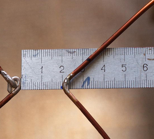
We clean the wire from insulation. Then bend the biquadrat with pliers. Let's see the pictures. All angles are 90 degrees.
Then solder the 75 ohm TV cable. We solder the core to one square, the braid to another.

The signal at high frequencies propagates along the surface of the conductor, so it is better to paint the antenna after assembly. I used leftover acrylic facade paint. It is better to fill the place of soldering with hot-melt adhesive or sealant.
We fasten the wire from the place of soldering with ties (straps) along the sides of the square, as in the photo. This mandatory action is antenna matching.
Testing a homemade antenna on a homemade TV
So the biquadrate gives a signal amplification of the order of 6 dB, and up to the tower 26 km in a straight line. Although the CETV website indicates that we are in the zone of a confident signal, I doubted and prepared what I had done a long time ago.
He climbed to the second floor of the house and pulled out the antenna to the scaffolding. He pointed towards the tower and turned on the TV. The TV confidently received both digital TV packages.
I brought a homemade antenna into the house, the TV continued to confidently show perfectly.

Gradually, everyone is abandoning analog television, giving preference to digital broadcasting. The largest providers are also restructuring to work with a newer, more modern format. The era of analog TV is gradually coming to an end.
In order for the previously installed home antenna devices to finalize the resource, it is enough to connect a DVB-T receiver to the TV, as a result, digital signals will be received correctly.
You can make an antenna for digital television with your own hands, so it is not necessary to go to the store and spend extra money. Any special skills or equipment will not be required; you can create the necessary design using improvised means.
Now we will answer in detail the question of how to make an antenna for digital TV. We will carefully analyze the process, select the optimal material, and also carry out all the necessary calculations. Nevertheless, first we will deal with the theoretical nuances.
Regardless of the signal format, it is transmitted from the emitters of the tower. Reception of the wave channel is provided by the antenna device. For reception digital signal you will need a sinusoidal device with the highest possible frequency, which is measured in MHz.
When electromagnetic wave passes through the surface of the receiving beams of the antenna, a V-voltage is induced in it. Each wave contributes to the formation of a different potential, marking it with its characteristic sign.

Under the action of an induced voltage, an electric current flows in a closed receiving circuit with resistance R. It is gradually increasing. Processing is carried out by the TV circuit, a picture is displayed on the monitor, and the sound is broadcast through the speakers.
With a conventional indoor antenna, it will not work. First, you will need an intermediate link that will provide information decoding - a DVB-T receiver. Secondly, you should use a UHF or Turkin antenna for DVB.

Antenna figure eight
How to make such an antenna with your own hands? First you need to prepare the material. Then carry out the corresponding calculations. At the final stage, assemble the structure and connect it to the TV. Nothing complicated. Each user will cope with this task.

Antenna Assembly Materials
Making an antenna for digital television is not difficult. The list of materials used will vary depending on the type of antenna device. For example, if you wish, you can make it even from the most ordinary beer cans.
To produce a good and simple TV antenna digital channels you will need copper or aluminum wire with a thickness of 2 to 5 millimeters. In general, it will take only 1 hour to create such a design. You also need to use:
- tube;
- corner;
- copper or aluminum strip.
V without fail you will need a tool that will allow you to bend the frames of the required shape. To bend the wire, use a hammer, after securing the material in a vise.

Do-it-yourself antenna is made not only from wire, but also from cable (coaxial). Choose a plug that will match your TV's jack. Naturally, you also need to fix the structure, the bracket is made from improvised materials.
As for the cable, it must be taken with a resistance in the range of 50-75 ohms. Special attention insulation should be given if the device is to be placed outdoors.
The specifics of fastening is determined in accordance with where the structure will be located. For example, residents of high-rise buildings will be able to make an antenna for digital TV themselves and hang it up like a home, i.e. on the curtains. This will require large pins that will serve as a fastener.

However, if you want to place the created device on the roof, then you need to make a bracket. To do this, you need a file, a soldering iron and a needle file.
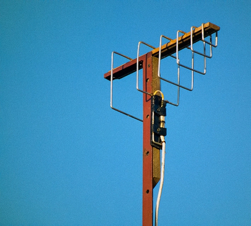
We figured out the spiral antenna, but you can also make another design - a double square. It is made from copper, brass or aluminum tubes. Less commonly used wire 3-6 mm thick. In general, the choice of material is determined according to the MW band and the number of channels.

Double square - two frames that are connected by an upper and lower arrow. The small frame is a vibrator, and the large frame is a reflector. For maximum gain, increase the number of frames to three. The third square is the director.
The mast must be made of wood. At least its upper part. Please note that it should start at a distance of one and a half meters from the level of the frames.
So, step by step instructions:
- Take your coax cable and strip both ends.
- One end will be attached to the antenna, the wire should stick out 2 cm.
- The screen and braid are twisted into a bundle.
- We get two conductors.
- Solder the plug to the second end of the cable. A distance of 1 cm is sufficient. If you use a crimped metal plug, you can skip further steps.
- Tin and make 2 more conductors.
- Wipe the soldering points of the plug with alcohol.
- Put the plastic part of the plug on the wire.
- A monocore is soldered to the central input of the plug.
- A stranded bundle is soldered to the side entrance of the plug.
- Crimp the grip around the insulation.
- Screw on the plastic tip or fill with glue.
Payment
To set up digital TV reception, it is not necessary to calculate the wavelength at all. Just try to make a broadband design. As a result, you can take maximum amount signals. To achieve this result, add additional elements to the T2 antenna with your own hands. It is about them that will be discussed further.

The calculation of the antenna for digital TV is based on the definition of the signal broadcast wave. Divide this value by 4 to get the required side of the square. To determine the distance between the two components of the device, make the outer sides of the diamonds a little longer, therefore, the inner ones, on the contrary, should be shorter.
If you don’t want to calculate the dimensions of the antenna yourself, use the ready-made drawings:
- The inner side of the rectangle is 13 cm.
- The outer side of the rectangle is 14 cm.
The difference in the distance between the squares, by the way, in no case should they be connected, the extreme sections provide the necessary maneuver for folding the loop. It is to it that the coaxial antenna wire is attached.
Antenna manufacturing
If we calculate the entire length, then in the end we get a value of 112 centimeters. Cut the wire or any other material that you plan to use, take a ruler and pliers, and begin to bend the structure. The angle must be 90 degrees. If the sides do not match in length, it's okay, a small error is acceptable.

Initial data for the manufacture of an antenna for digital TV:
- The first element is 13 centimeters and 1 centimeter per loop, by the way, it can be bent immediately.
- Two elements of 14 centimeters.
- Two by 13 centimeters, but at the same time there should be a turn in the opposite direction, here an inflection is created to another square.
- Two more plots of 14 centimeters.
- The last one is identical to the first one.
Do-it-yourself digital TV antenna frame is ready. If you did everything correctly, then between the 2 halves in the middle there was a gap of several centimeters. Naturally, there may be minor differences. After that, the loops and kink areas must be cleaned until the metal is visible. Processing is carried out with fine-grained sandpaper. We connect the loops, crimp with pliers to fix their position.
The design itself is ready, but in order for the antenna made for T2 to function correctly, the cable must be processed. We start with double-sided stripping of the wire. One end will connect directly to the antenna. It is necessary to strip the cable in this section so that the cord sticks out about two centimeters. If it turned out a little more, the rest can simply be cut off in the future.

We twist the screen and the cable braid into a bundle, as a result we get 2 conductors - the central core and a twisted element of several braid wires. All this needs to be tinned.
Using a soldering station, solder the plug to the second edge of the cable. A centimeter length is enough, small errors are permissible. According to the principle described earlier, you need to make a pair of conductors and tin them.
The plug is placed in those areas where soldering will be carried out in the future, wipe it first with alcohol or a special solvent. Then, using a file or emery, we clean up. Attach the plastic plug to the cord. Now start soldering. Attach a core to the central entrance, and a multi-core braid to the side entrance. Crimp the grip around the insulation.

Screw on the plastic tip, some experts even fill it with glue or a special sealant to enhance fixation. While the fixing base has not hardened, quickly assemble the plug by screwing on the plastic part, and then remove excess adhesive or sealant. As a result, it will be possible to maximize the service life of the plug. Homemade created, it's time to connect it.
Connection
Connect the cable and frame of the homemade DVB T2 antenna. It is not necessary to bind to any particular channel, so solder the cord in the middle. As a result, a broadband antenna will be created that receives the maximum number of TV channels. Solder the second split end of the wire to the other two sides again in the middle, you previously stripped them and also tinned them. To extend the reception range, do not solder the cable from below.
When the design is assembled, it must be checked. We connect the tuner and turn on the TV. If digital television catches, for example, it was possible to set up 20 channels, you need to finally complete the assembly. Fill with sealant the areas where soldering was carried out.

However, if there are very few active channels or there is some interference, then you need to find a place where there will be an optimal signal. If there is no positive change, change the antenna cable. To simplify the testing process as much as possible, use a telephone wire, it is quite cheap. Solder the plug and frames to it. If the signal quality has improved, then the problem is really in the cable. will broadcast channels even if noodles are used, but as practice shows, its service life is extremely limited.
To protect the cable connection areas and antenna frames from precipitation and other atmospheric influences, wrap the soldering points with the most common insulating tape. However, this is not a durable solution. A more effective option is to install heat shrink tubing on the soldering areas, which will provide proper insulation.

An alternative option that has maximum reliability is glue or sealant. The fact is that these substances do not conduct electricity. Be sure to make a housing for the antenna, the most ordinary plastic cover is suitable for this. If necessary, make indentations so that the frame “lies down”, do not forget about the cord output. Pour the sealant and wait until it dries. Everything is ready, we connect the equipment and enjoy digital TV.
Double or triple square for weaker signal
The TV antenna is used in villages, dachas and in areas that are on the border of the coverage area of television towers. The device allows you to receive even a very weak signal. If you do everything right, then the power of the TV signal will increase noticeably.
A double or triple square has only one drawback - you need to direct the design to the signal source with maximum accuracy. Therefore, if you do not know exactly where the tower is located, difficulties will arise.

The number of frames determines the quality of the signal. Therefore, if you are outside the coverage area, you can not be limited to 2-3 frames, you can do 5. You should not open the antenna with varnish or paint it. This negatively affects the quality of signal reception.
What are strengths designs? First of all, the quality of reception. Even if you are away from the repeater, the signal will be clear. However, it will be possible to achieve a positive result only if the user correctly determines the dimensions of the frames and the matching device.
materials
To make an antenna for digital TV yourself, you need to prepare materials that will later be used to make the structure. An antenna is made of metal tubes or wire:
- 1-5 channel of the meter range - copper, brass, aluminum tubes with a thickness of 10-20 millimeters;
- 6-12 meter range channel - copper, brass, aluminum tubes 8-15 millimeters thick;
- decimeter range - copper, brass wire with a thickness of 3 to 5 millimeters.

Double square - 2 frames that are connected by a pair of arrows (upper and lower). The smallest frame is the so-called vibrator, and the largest one is the reflector. A device with three frames will have a large TV signal gain. The third square is called the director.
Instructions for creating an antenna T2:
- The upper arrow (made of metal) must connect the middle of all frames.
- The lower boom is made using electrically insulating materials: wood, textolite.
- Position all frames so that their centers are on the same straight line.
- Direct should be sent to the repeater.
- The vibrator must be open-loop. Its edges are fixed on a textolite plate.
- If you made frames from metal tubes, then the edges should be flattened, and holes should be made in them to fix the lower boom.
- The mast must be made of wood, or at least its upper part.

Size calculation
The calculation of the antenna for digital TV will directly depend on the range - meter or decimeter. The dimensions of the antenna with three frames are characterized by a large distance between the ends of the vibrator. It is necessary to leave more distance - 50 millimeters.

The tables show the dimensions of the two-element loop antennas. Meter range:
|
Channel numbers |
||||||||||||
Decimeter range:
The size of the three-element antennas. Meter range:
|
Channel numbers |
||||||||||||
Decimeter range:
Vibrator connection
Given the fact that the frame is symmetrical, and the connection is made to an asymmetric antenna cable, a matching device must be used. The best option- short circuit. It is made from pieces of coaxial cable. The left segment is the feeder, and the right one is usually called the loop. In the place where the feeder and the cable will be connected, we fix the cable, which is later connected to the TV.
What should be the length of these segments? The calculation is carried out in accordance with the long wave of the received TV signal.

At one end, you need to cut the cable by removing the aluminum screen. The braid must be twisted into a tight bundle. Cut off the center conductor to the insulation. The feeder also needs to be cut. Remove the shield made of aluminum, and then twist the braid. However, we leave the central conductor.
The further assembly process is carried out as follows:
- Solder the cable braid and the feeder conductor to the left edge of the vibrator.
- Solder the feeder braid to the right edge of the vibrator.
- With a metal jumper, the cable braid is connected to the lower end of the feeder. You can also fasten these elements with metal wire. The main thing is that there is proper contact with the braid.
- The braid determines not only the electrical connection, but also the distance between the sections of the matching device.
- If there is no metal wire and jumper, then twist the braid into a bundle lower part loop, after removing the screen and removing the insulation. To ensure proper contact, you need to solder the bundles using solder that melts easily.
- Pieces of cable should be parallel to each other. Distance - 50 millimeters (small error is acceptable). To fix the distance, special clamps made of electrically insulating materials are used. It is also possible to fix the matching device to the textolite plate.
- The cable that is inserted into the TV socket should be soldered to the feeder (to the bottom). The braids are interconnected, as are the central conductors.
To reduce the number of connecting elements, the feeder and the cable connected to the TV can be made one. Remove the insulation at the point where the feeder ends. This is done in order to carry out the installation of the jumper.

The matching device is a mandatory element that helps prevent interference. It will be especially useful if the signal transmitter (TV tower) is located at a great distance.
butterfly antenna
A TV antenna can also be made in the form of a butterfly. Such a device will be in no way inferior to a decimeter antenna. It is not necessary to do everything from scratch. It's much easier to convert a conventional grille to a digital one for T2 tuning. To make it yourself, follow these simple instructions:
- Take a small board, which will become the basis of the future antenna.
- Cut 8 wires, each 37.5 centimeters long.
- The middle of all wires must be stripped by about 2 centimeters.
- Bend the wires to accept V-shape. The distance between the wires should be 7.5 centimeters.
- Cut 2 more wires, each of them should be 22 centimeters long.
- Strip the wires where they will be attached to the antenna base (board).
- Place the self-tapping screws along the base of the antenna, and then connect the V-shaped elements with two wires.
- Connect the antenna and cable using the special plug.

Each user can create such a device. You won't have to buy anything. An antenna is made from improvised means.
From coaxial cable
You can actually manually make a TV antenna using a cable:
- Cut approximately 530 millimeters of cable.
- Strip the cable from both sides, fastening the braid into a bundle and exposing the central core.
- Twist the cable into a ring or rhombus, securing it with tape to the plywood. The distance between the cable rings should be 2 centimeters.
- Cut a piece of coaxial cable - 175 centimeters. Make a horseshoe-shaped matching device out of it. To do this, you need to strip the wire from both ends, as you did in the process of making rings.
- Prepare the antenna cable. On one side, a plug is put on, and the second is cleaned. It is necessary to remove the central core and braid.
- Align the ring and matching device with antenna cable.

As a base, you can use not only plywood, but also plexiglass.
can antenna
To make a simple TV antenna for digital channels, you will need a cable, a couple of aluminum or tin cans, and a small plastic pipe. A wooden plank can also be used as a base.
Remember that the antenna can only be created from aluminum or tin cans. Plastic or glass will not work. The main requirement is smooth, not ribbed inner walls. Everyone will be able to mount such a device with their own hands in just a few minutes.
- Rinse well and then dry the jars.
- The end of the coaxial cable must be cut.
- Remove the insulation central vein.
- Twist the braid.
- Having received 2 conductors, attach them to the banks.
- If you have a soldering iron handy, solder the wires. They can also be fixed with flat head screws. Twist the loop at the ends of the conductors, and thread a self-tapping screw with a washer in it, then fix it on the bank.
- Pre-clean the metal, you need to take a fine-grained sandpaper and remove plaque, as well as paint.
- Attach the jars to a plastic pipe or wooden plank.
- The distance is calculated individually.
- Connect the cable to the TV and try to tune in the channels.

This is an emergency solution. Have no illusions at best good quality multiple channels will be available. The final result directly depends on how far the TV tower is, what is the “cleanliness” of the corridor, and also how well the antenna is made.
Now you know how you can make an antenna for using improvised means.
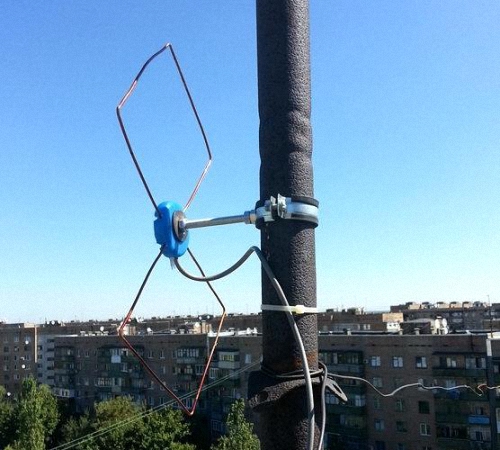
The popularity of the Internet among the population is constantly growing. However, many people live in places where the signal is very weak or non-existent. In this regard, the problem of increasing the power and quality of Internet reception is very acute. Slow speed takes a lot of time and does not give the desired result. Therefore, an external Kharchenko antenna often comes to the rescue, designed in the form, the material for which is a thick copper wire. The connection with a square between themselves occurs in places of open corners, where the connection is made television cable.
Such an antenna requires an accurate calculation for digital terrestrial television. To improve directivity, some designs may have a grating or solid screen of conductive material. Such a biquad antenna allows you to solve many problems with signal reception and Internet speed. Homemade designs, including different types Kharchenko's antennas are relatively easy to manufacture and include metal and plastic parts, as well as elements of other materials, connected different ways. Similar designs are easily made on their own, including the Kharchenko antenna for TV with their own hands.
Harchenko antenna for modem
Currently, many users seek to increase the speed of their mobile internet. This problem is especially acute for those who live at a considerable distance from the base station, using the Internet at a very low speed. In such situations, the best way out is the Kharchenko antenna for a 3g modem with your own hands, which is quite easy to make at home.
This framework is known as UHF antenna since the 60s of the last century. It has a zigzag frame configuration, which makes the device very efficient.
The system consists of two square elements. In order to calculate the antenna for a 3g modem at a frequency of 2100 MHz, the size of each side of the square should be 53 mm. The whole structure is made in the form of an interlocked structure, which includes two diamond-shaped figures with inside corners 1200. This is done in order to reduce the internal resistance of the device. The connection of rhombuses is carried out by soldering. The high-frequency cable is also soldered here.
More accurate data can be obtained using online calculator to calculate the Kharchenko antenna, in which you just need to enter the necessary initial data.

To increase efficiency, the device can be used in conjunction with a reflector. Usually this part is a metal plate, and foil textolite is the most suitable material for its manufacture. In this case, the antenna includes determining the distance between the receiver and the reflector. After calculations and procurement of materials, a do-it-yourself Kharchenko antenna for the modem can be made.
The parts are connected to each other with the help of hot glue. You can fix the desired distance between the elements using any object with the most suitable sizes. Then the antenna is connected to the device. Since modems do not have connectors for connecting external antennas, they are simply wrapped with wire, which is then connected via a cable to the receiving device. If necessary, the Kharchenko antenna for a 4g modem can be made according to the same scheme.

Upon completion of the assembly, at the opposite end of the cable that will be connected to the modem, you need to assemble the so-called matching device, which is provided specifically for such devices. For this purpose, copper foil is used, the same as in printed circuit boards. The performed antenna calculation for a 4g modem is the same as in the previous version.
If there is a connector for an external antenna, the cable is connected using a special adapter. After all connections, the antenna for the modem is considered ready for use. Setting the signal reception for 4g is carried out experimentally, by slowly rotating the structure around the axis until the clearest signal is obtained. Signal quality is determined by the number of dashes on the icon displayed on the computer or mobile phone.
Antenna Kharchenko for digital TV
For the operation of digital television, a range of decimeter waves is used. Therefore, before designing, Kharchenko antennas for DVB t2 should be made in order to maximize signal reception.
The design itself looks quite compact, it is made in the classic version of two rhombuses, as a result, a zigzag antenna without a reflector is obtained. Any conductive material can be used as a base, for example, a copper or aluminum conductor with a diameter of 1-5 mm. Tubes, strips, corners, profiles, etc. are also suitable. Copper wire 3 mm thick is best suited for these purposes. It is very easy to bend, level and solder. Further, it must be made in a certain sequence. TV cable resistance should be approximately 50-75 ohms.

The quality of a digital signal does not depend on distance, as it happens in analog television. In this case, when the TV antenna is working normally, the signal normally enters the TV receiver, but if there are failures, then there will be no signal at all. Accordingly, there will be no image. If there is a signal and it is normally received, then the image will be of the same quality on all channels. This factor must be taken into account when performing for digital TV, although individual settings may be different for a particular region.
Kharchenko's television antenna itself is made in a certain sequence:
- First you need to measure a piece of wire with a total length of 112 cm and bend it, observing the dimensions of the sections alternately 13 and 14 cm.
- After all the bends, two ends are formed, which must be cleaned to a distance of 1.5-2 cm. Loops are made at the ends and fixed to each other. The joints are completely soldered. Then, the central core is soldered to one of the joints, and the braid to the other. The result is a finished antenna or a double square.
- A biquad TV antenna requires a TV cable of approximately 3 meters. From the side of the antenna, it is stripped by 2 cm, and from the side of the plug - by 1 cm. The plug can be chosen at your discretion. It, like the wire, needs to be cleaned with a needle file or some kind of sharp object. Thus, Kharchenko's zigzag antenna for digital TV is almost ready for use.
- After soldering, all joints should be filled with hot glue from a gun. While the glue has not cooled down, its excess must be collected. It turns out at the same time reliable and elastic connection. On the antenna itself, the soldering points are also filled with glue.
Kharchenko antenna for phone
An external directional antenna can significantly increase the capabilities of a mobile phone and improve the quality of communication when a subscriber is in a remote area. It is not always possible to find the most suitable option on sale, so the Kharchenko antenna becomes the best way out for cellular communication made from improvised materials with their own hands.

The most affordable option is the standard design discussed above. Such an antenna should be sized according to the specific operating conditions. Everything necessary materials sold at a hardware store. The simplest designs can be directly connected to the cable and do not require any special settings.
First of all, it is necessary to stock up on copper wire, with a diameter of 2-3 mm. You can take an insulated wire and remove the insulation from it. If connections are to be made without soldering, special F-type antenna connectors and connectors will be required. When it is planned to connect two Kharchenko antennas in parallel, you may need a reflector, which can be tin or aluminum. Joints are insulated with heat shrink tubing or electrical tape. Soldering requires a soldering iron.
Copper wire, prepared in advance, is bent and turns into a zigzag frame, which is two rhombuses. The sides of each of them are 80 cm long, and the total distance between opposite corners will be 226 cm. Next, the antenna calculator determines the connection point of these diamonds as the junction with the cable. A piece of cable, 50 cm in size, is soldered to this point, and an F-type connector is screwed to its opposite end. Next, the main cable of the required length is connected to the connector.

In some cases, the calculation of the Kharchenko antenna online involves the installation of a reflector that significantly enhances signal reception in a certain area. The design is the same as the antenna for T2, when the lower end of the frame and the reflector are connected to each other through the cable braid. For this purpose, a bolt 50 mm long is additionally screwed into the reflector, to which an F-type connector is attracted with a tie. Beforehand, a cable and a frame located at a distance of more than 40 mm are soldered to this connector. Thus, Kharchenko's antenna for a mobile phone, made independently in the most simple version, ready to use.
For direct connection of the receiving device with a mobile phone, a pigtail is used, which is a special wire. One end is connected to the antenna cable, and the other end is connected to the phone's antenna jack using a connector. In this case, there is no problem to calculate the antenna and no separate settings are required, it is enough just to position the antenna in the most optimal way, focusing on the quality of the received signal. It is recommended to install the mast with the receiving device as close to the house as possible, preferably near the window, in order to minimize the length of the cable.
V general case the calculation of the reception range is extremely complicated. Dozens of factors are superimposed on the reception range, including even the time of year and day.However, especially for residents of Moscow, we present 3 boundary graphs (Fig. 1) for receiving digital DVB-T2 packets (multiplexes).
All 3 graphs are built for 3 reception conditions:
1 – long-range reception (receiving antennas with a gain of 16-18 dB, class "long-range");
2 – average reception (receiving antennas with a gain of 10-12 dB, class of balcony antennas);
3 - short-range reception (indoor antenna "Delta").
In all cases, it is assumed that either an active antenna with a built-in mast amplifier is used, or an external low-noise mast amplifier (F=2 dB) is used. Of course, the use of more expensive "long-range" antennas will provide much better (reliable) reception even under all weather conditions and for many years of operation. The higher the price of the antenna, the more attractive it is. appearance and great durability in use.
Drop cable length at the presence of a mast amplifier(of any type) does not matter either to the quality of reception or to its "range". At no mast amplifier the length of the drop cable (especially when working on 2 or more TVs) is already very important.
When using indoor antennas(Gain = 6 dB) it must be remembered that walls (and radio waves will most likely pass through a window opening or walls) have shielding (attenuation of radio waves). The radio shielding factor of 6 dB was assumed in the calculations. In practice, it can reach 14 ... 18 dB. In other words, this means that the actual range can be reduced by a factor of 2-3, depending on the location of the indoor antenna and the shielding factor of the walls.
Curve with Gain=0 dB corresponds to widespread active indoor foreign antennas (as a rule, they are powered by mains voltage ~ 220 V / 50 Hz). Such antennas have zero gain (without a built-in amplifier), but are quite aesthetic in appearance.
For residents of the regions the figure below shows similar dependences of the reception range R 0 depending on the height of the receiving antenna h for different installation heights of transmitting antennas - H. The curves are plotted for "long-range" antennas with a radiated transmitter power of 4 kW at a frequency of 600 MHz.

If your real transmitter power P differs from 4 kW, then the calculation of the real receiving range must be adjusted according to the formula: It is useful to note that if the height of the receiving antenna is more than 15 meters, then it is possible to calculate the reception range R for a height of 15 m, and then recalculate according to the formula:
 So, for a receiving antenna height of 30 meters, the reception range increases by about 1.4 times (for example, from 48.3 km to 68.1 km).
In conclusion, we present a number of useful practical advice for digital DVB-T2 reception:
Tip 1
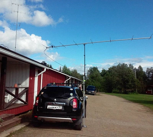
At present, it does not make practical sense to install bulky MW antennas. Taking into account the appearance of digital DVB-T2 broadcasting, it is more profitable to spend money on one single high-quality UHF antenna complete with a built-in or externally connected mast amplifier.
Tip 2
Choose a mast amplifier with gain 12-20 dB and minimum noise figure (no more than 3 dB). If you buy a mast amplifier on the market, then consider the fact that non-specialists trade there. Therefore, without listening to their recommendations, try to choose an amplifier with a maximum current consumption (about 40-70 mA). More current consumption corresponds to a greater dynamic range (distortion minimization).
Tip 3
Try to make sure that the mast on which the antenna is mounted is grounded. Desirable install a lightning protection device between the antenna and the mast amplifier. If reception is carried out in a house where a regular lightning protection system is already provided, then you will not need any additional system.
Tip 4
Desirable choose an antenna with the highest possible gain. This criterion for the UHF range when receiving digital DVB-T2 signals is the main one. Other things being equal, choose an antenna with a minimum wind load and weight.
Tip 5
Try to minimize the length of the drop cable (between the antenna and the first amplifier). Drop cable length 5-10 meters for most practical applications considered acceptable.
Tip 6
Conveniently use a mast amplifier with a supply voltage of 5 V instead of traditional 12 V or 24 V. A 5 V remote power supply is present in almost every DVB-T2 receiver, which is very convenient, because. no additional power supply required.
Tip 7
For normal readability of digital DVB-T2 packets, a signal level at the antenna output of 36 dBuV is quite sufficient. Mast amplifier serves only to compensate for losses in a drop cable and a splitter for several TVs.
Tip 8
To increase the reception range choose a receiving antenna With maximum possible gain and install it if possible. as high as possible relative to the earth's surface. The mast amplifier should be located as close to the antenna as possible or an active antenna should be purchased immediately.
The main indicator of the quality of each antenna is its interaction with the on-air signal. This principle of operation underlies both purchased and homemade antennas. We suggest that you familiarize yourself with the recommendations on how to make an antenna for digital TV with your own hands.
Features of modern television
If we compare the modern television broadcast with the broadcast that was a few years ago, we can find certain differences. First of all, the UHF range is used for broadcasting. Thus, it is possible to significantly save money and signal reception by the antenna. In addition, in this case, the need for periodic maintenance of the antennas is also eliminated.
Also, there are many more television sensors than before, so most TV channels are available in almost all places in the country. To provide television broadcasting in habitable areas, low-power sensors are used.
In large cities, radio waves propagate differently. Because of a large number multi-storey buildings, the signal through them is weak. In addition, there is great amount television channels, for which one standard television antenna is not enough.
With the development of digital broadcasting, receiving channels has become even easier. These types of antennas are resistant to interference, phase or cable distortion, image clarity.
DIY simple digital antenna: device requirements
Since the broadcasting conditions have changed, the rules for operating modern antennas have changed:
1. One of the main parameters of a television antenna, in the form of a directivity factor and a protection factor, are not particularly important. To combat various kinds of interference, various electronic means are used.
2. The coefficient responsible for the gain of the antennas improves the signal, clears it of extraneous sounds and various kinds of interference.
3. Another important quality of a modern television antenna is range. Saving electrical parameters is carried out automatically, without additional human intervention.
4. The operating range of the television antenna should interact well with the cable that connects to the antenna.

5. In order to avoid the appearance of phase distortions, it is necessary to ensure decent antenna characteristics in the amplitude-frequency ratio.
The characteristics of the last three points are determined by the properties for receiving a television signal using an antenna. An antenna operating at one frequency is capable of receiving several wave channels. However, in order for them to be coordinated with the feeder, it is necessary to have OSS that strongly absorb signals.
Therefore, there are certain variants of digital antennas available for making at home. We invite you to familiarize yourself with them:
1. All-wave version of the antenna, such devices are frequency independent, they are cheap, very popular among consumers. One hour is enough to make such an antenna. Such an antenna is perfect for city apartments, but in locality, which is somewhat distant from television centers, such an antenna will work worse.
2. Speech therapy band version of the antenna - such an antenna picks up certain signals. It has a simple structure, is well suited for various operating ranges, does not change the parameters of the feeder. Differs in average technical parameters, great for country houses, cottages, apartments.
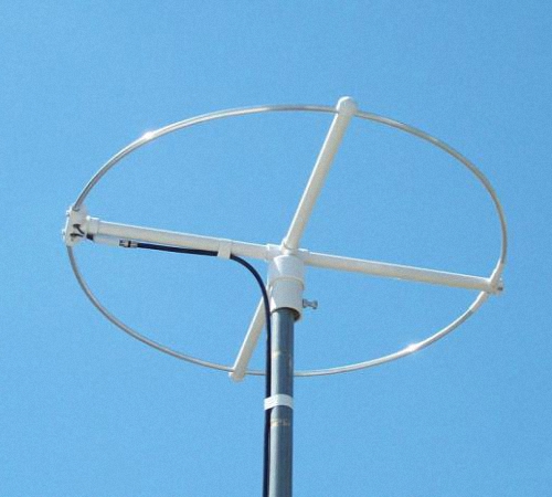
3. Z-shaped antenna, which is also called a zigzag. For the manufacture of such a design will require a lot of time and physical effort. Differs in wide receiving characteristics. With the help of such an antenna, it is possible to expand the range of reception of television channels.
To achieve an exact match between the antennas, it is necessary to lay the cable through the zero potential value.
Do-it-yourself digital TV antenna: reception characteristic
Vibratone antennas are capable of finding several more digital ones on one analog channel. Such devices receive wave channels. They are rarely used and are relevant for places remote from television towers.
Self-manufacturing satellite dish is a pointless process. Since in this process you will need to purchase a purchased tuner and head, and the mirror alignment must be very accurate, it is almost impossible to achieve it at home. You can only configure such an antenna yourself, but not its manufacture.
In order to make the above antenna options, you need to be very well versed in higher mathematics and electrodynamic processes. Among the main characteristics of the terms used in the manufacturing process television antennas, note:
1. KU - antenna power, which is determined in the ratio of the received antenna signal to its main lobe.
2. KND - the relationship between the solid circle and the solid angle of the antenna lobes. If there are lobes of different sizes, they change in area.
3. KZD - the ratio between the signal received on the main lobe and total amount antenna power.
Please note that if the antenna is a band antenna, then the power is taken into account in relation to the useful signal.
Note that the first two terms are not necessarily interdependent. There are certain variants of antennas that have a high directivity, but unity or less gain. However, in a zigzag antenna, significant gain is coupled with a low level of directivity.
Do-it-yourself digital TV antenna: manufacturing technology
Each of the antenna elements, through which the current flows, giving a useful signal, must be connected to the other by soldering or welding. Any prefabricated assembly located on the street must be well fixed, since the destruction of the electronic contact on the street occurs faster than indoors.
Particular attention should be paid to zero potential. It is in these places that the nodes of stress are located, electricity, at its highest power. For the manufacture of places with zero potential, one-piece bent metal is used.
For the manufacture of the braid or the central core, a coaxial cable is used, made of copper or an inexpensive alloy with anti-corrosion properties. For soldering the cable, a forty-volt soldering machine is used, with low-melting solders and flux paste.
Do-it-yourself outdoor digital antenna is made in such a way that all connections are resistant to moisture, temperature changes and other environmental influences.

To make an all-wave antenna, you will need two triangular plates, two rails made of wood and enameled wire. At the same time, the size of the wire in diameter is practically not important, and the interval between their ends is about 2-3 cm. The interval between the plates on which the ends of the wire are located is 1 cm. Two metal plates can be replaced by a one-sided square-shaped fiberglass coated with foil. At the same time, copper triangles should be cut out on it.
The antenna width should be the same as the height. Cloths open at a right angle. In order to lay the cable to this antenna, you must follow a certain scheme. The cable braid is not soldered to the point indicating zero potential. She's just attached to her.
CHNA, which stretches inside the window by 150 cm, is able to receive most meter and DCM channels in any direction. The advantage of this antenna is that it has a wide channel reception interval. Therefore, such antennas are popular in big cities, where there are various television centers. However, such an antenna has certain disadvantages - the KU of the antenna is single, and the KZD is zero. Therefore, in the presence of large interference, the antenna will be irrelevant.
It is possible to make other types of digital antennas with your own hands with a CNA, for example, a logarithmic spiral of two turns. This version of the antenna is compact and easier to manufacture.
Essential digital antennas with hands from beer cans
To make a digital antenna with your own hands from a cable, you will need beer cans. This version of the antenna, with the right approach to its manufacture, has good performance characteristics. In addition, such an antenna is quite simple to manufacture.
The principle of operation of such an antenna is based on an increase in the diameter of the arms on a conventional linear vibrator. In this case, the working band is expanded, while other properties do not change.
Beer cans in relation to their size are used as arms on a vibrator. At the same time, the expansion of the shoulders is unlimited. This version of a simple vibrator is used as a do-it-yourself indoor digital antenna for receiving television broadcasts by connecting directly with a cable.
If we dwell on the option of assembling an in-phase grating from a beer dipole, located vertically, with a step of half a wave, then it will be possible to improve the gain value of the antenna. Also, an amplifier from the antenna must be installed on this device, with the help of which the device is coordinated and tuned.

To enhance such an antenna, a KZD is added to it, a screen and a grid installed on it at the back, with an interval of half the grating. To install a beer antenna, you will need a dielectric mast, while the screen and mast are connected by a mechanical connection.
At the same time, about three or four rows are arranged on the grate. Two gratings are not capable of achieving much gain.
DIY UHF antenna for digital television
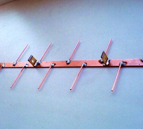
A log-periodic version of the antenna is called a prefabricated type antenna, which is connected to the halves on a linear dipole, the interval between them changes, in relation to the geometric parameters of the progression. There are configured and free lines. We propose to dwell on a longer and smoother version of the antenna.
For the manufacture of LPA, it is necessary to have any predetermined range. The higher the progression, the greater the gain of the antenna. This version of the antenna for operational and technical specifications is ideal for making at home.
The main principle of its normal functioning is to conduct correct calculations. With an increase in progressive indicators, the gain increases and the opening angle of the directivity decreases. This antenna does not need an additional screen. Since it does not depend on its general characteristics.

In the process of calculating a digital LP antenna, use the following recommendations:
- the second longest vibrator must have a margin of frequency power;
- then the longest dipole is calculated;
- after that, another specified frequency range is added.
If the shortest dipole leaves lines, then it is cut off, as it is needed on the antenna, only for calculations. The total length of the antenna will be about 40 cm.
The diameter of the lines on the antenna is about 7-16 mm. In this case, the interval between the location of the axes is 40 mm. The cable is not tied to the line by the external method, as this will adversely affect the technical properties of the antenna.
The outdoor antenna is fixed on the mast using the center of gravity. Otherwise, the antenna will constantly shake under the influence of the wind. However, the metal mast is not connected to the line in a straight line, since a dielectric mast must be provided at this point, the length of which is about 150 cm. As a dielectric material, you can use wooden beam previously painted or varnished.
DIY digital antenna video: